


3-30
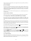
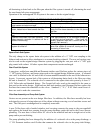
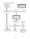
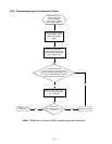
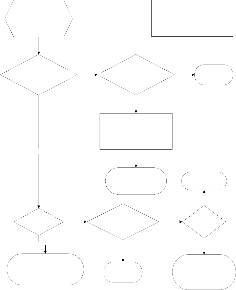
3.8.1 Troubleshooting the 24VAC Circuit
UNIT IS CONNECTED TO
POWER SUPPLY, DRAIN
VALVE IS FULLY
CLOSED, CONTROLLER
IS ON AND CALLING
FOR HEAT (heat mode
indicator is illuminated).
NOTE: All voltage measurements must
be made within 4 seconds of unit calling
for heat. If unit does not fire within 4
seconds, ignition modules will lock out
and the computer must be turned off then
back on to reset.
Is 24VAC
present on interface
board J3 pin 9 (LED 5 (GV)) and,
on dual vat units, J1 pin 9
(LED 1 (GV))?
Is 24VAC
present across gas valve main
coil (PV terminal) (on both valves
if dual vat)?
Yes
24V circuit is OK.
Problem may be
with gas valve.
Yes
Probable causes are an open high-limit
or a failed wire between the interface
board and the gas valve. On units with
built-in filtration, cause may also be a
failed drain safety switch.
No
Check continuity of high-limit and
continuity of drain safety switch.
If both are zero,
problem is in wiring.
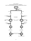
Is LED 3 (24V)
lit continuously?
No
Probable causes are a failed
24V transformer, failed
wiring between transformer and interface
board or fuse on 106-0386 interface
board.
No
Is 24VAC
present on the right PWR
terminal (LED 4) (and left PWR
terminal (LED 2), if
dual vat)?
Yes
Probable cause
is a failed interface
board.
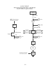
No
Is 24VAC
present on V1S (or
V1D and V2D, if
dual vat)?
Yes
Probable cause is a
failed interface board.
Yes
If ignition module fuse
is good, probable causes are a
failed ignition module or a failed
interface board. Replace suspect
ignition module with one known
to be good to isolate cause.
No