


6-5
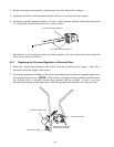
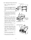
5. Loosen the small compression nut in the large fitting on the replacement thermostat so that the
large fitting will move freely on the capillary tube (the thin, flexible tube). Carefully insert the
replacement thermostat into the cookpot, being careful not to bend the thermostat tube. Position
the tube along the inside of the left leg of the element (as viewed from the front of the cooker)
and secure it in place with two metal wire ties. Apply thread sealer to the large fitting and screw
the fitting securely into the cookpot. When the large fitting is tight, pull gently on the capillary
tube to remove any slack, then screw the small compression nut into the large fitting and tighten.
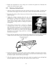
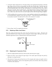
6. Coil the capillary tube as necessary to achieve a neat installation and attach the terminal block to
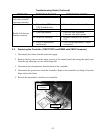
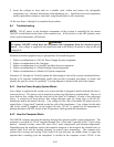
the mounting bracket using the screws removed in Step 4. Connect thermostat lead 5C (black) to
the normally closed (NC) terminal and 8C (white) to the common (C) terminal.
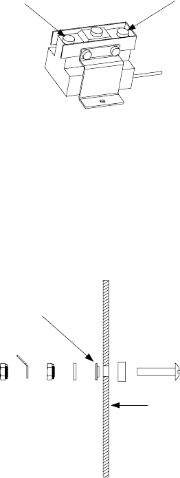
Common (C) Terminal
(Note open side.)
Normally Closed (NC) Terminal
(Note closed side.)
7. Reverse Steps 1 and 2 to complete the procedure.
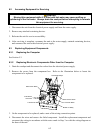
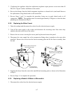
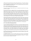
6.3.5 Replacing a Water-Level Sensor
Drain the cookpot and disconnect the cooker from the electrical power supply. Disconnect the
sensor lead from the sensor, remove the nuts securing the sensor in place, and remove the sensor.
Install the replacement sensor as illustrated below and reconnect the lead.
Insulator must seat in
hole before nut is
tightened.
Inside of cookpot.
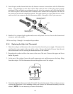
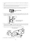
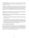
6.3.6 Replacing the Temperature Probe
1. Drain the cookpot and disconnect the cooker from the electrical power supply.
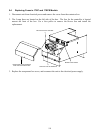
2. Remove the three screws along the upper edge of the control panel and open the panel by
allowing it to swing downward.
3. Disconnect the 15-pin connector from the rear of the computer and, using a pin pusher (such as
Frymaster P/N 806-4855), push out the temperature probe (red and white) leads from positions
13 and 14 on the connector.