


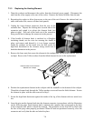
7-12
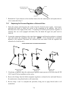
7.4 Troubleshooting
Problems with this equipment may be grouped into five broad categories:
1. Failure or malfunction of a 24VAC Power-Supply System component.
2. Failure or malfunction of a Control System component.
3. Failure or malfunction of an Autofill/Autoskim System component.
4. Failure or malfunction of a Water Heating System component.
5. Failure or malfunction of a Basket Lift System component (on units so equipped).
Sections 7.4.1 through 7.4.5 briefly explain the functioning of each of the systems mentioned above.
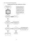
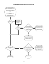
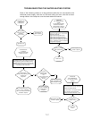
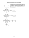
Section 7.4.6 contains troubleshooting guides that provide systematic procedures to isolate and
identify the specific source of a problem. Wiring diagrams are located at the end of the chapter.
7.4.1 How the Power-Supply System Works
Line voltage is supplied to the system via a power cord that is plugged or hard-wired into the store’s
electrical service. The power cord is attached to a three-lug power terminal block. One set of three
wires delivers line voltage from the load side of the block to the line side of the contactor. A second
set of two wires delivers line voltage to the 24VAC transformer. Line voltage for the heating
element is delivered from the load side of the contactor through the 6-pin connector on the rear of
the contactor box. 24VAC for the remaining components is distributed to and from the contactor
box via the 15-pin connector on the front of the box.
On units with basket lifts, a separate set of two wires delivers line voltage from the terminal block to
the basket lift 24VAC transformer. From the transformer, the 24VAC is delivered to the interface
board via the 12-pin connector on the interface board. Line voltage for one side of the basket-lift-
motor circuits is delivered directly to the motors from the terminal block via the 15-pin connector on
the front of the contactor box. Line voltage for the other side of the basket-lift-motor circuits is
supplied via the basket lift relays mounted on the interface board through the 5-pin connector on the
interface board. All line and 24VAC power except the line voltage for the elements is distributed to
and from the contactor box via the 15-pin connector on the front of the box.
7.4.2 How the Computer Works
The CM III computer provides the interface between the operator and the system components.
24VAC from the transformer is supplied through Pin 7 of the 9-pin connector on the interface board.
The 24VAC is rectified to 12VDC and delivered to the computer via Pins 1 and 3 of the 15-pin
connector. Internal circuitry senses the water temperature. Depending upon the conditions sensed,
the computer energizes or de-energizes the heating element (via the contactor coil) to control water
temperature. The computer also controls the lowering and raising of the basket lifts, and activates an
audible alarm to signal the operator that a cooking cycle has completed. The computer signals for
heat via Pin 4 of the 15-pin connector. The temperature probe connects to Pins 13 and 14 of the 15-
pin connector. The basket lift relays connect to Pins 7 (right) and 9 (left), and the sound device
connects to Pin 11 of the 15-pin connector.