


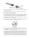
7-13
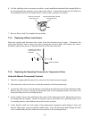
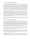
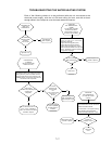
7.4.3 How the Autofill and Skim Systems Work
The heart of the automatic filling (Autofill) system is a normally closed solenoid valve that opens
when 24VAC is applied as a result of the loss of upper water-level sensor ground. The ground is lost
when the sensor is not in contact with water in the cookpot. Starch or lime build-up on the sensor
may keep a ground from forming. Therefore always make sure the sensor is clean and its lead is
firmly connected to Pin 1 of the 6-pin connector on the interface board (units with manual controls)
or connector J5 on the interface board (units with computer controls). Also, in order for the ground
to form, there must be some mineral content in the water (pure water is non-conductive).
Consequently, the units will not operate with distilled water. If distilled, highly filtered, or purified
water is used, add ⅛-cup of baking soda to the water each time the cookpot is emptied and refilled.
In units with manual controls, the 24VAC is supplied via Pins 1 and 2 of the 4-pin connector on
the interface board so long as the upper water-level sensor is not in contact with the water in the
cookpot. In units with computer controls, 24VAC is continuously supplied to one leg of the
circuit via Pin 6 of the 15-pin connector on the front of the contactor box. The other leg is supplied
via Pin 2 of the 12-pin connector on the interface board so long as the upper water-level sensor is not
in contact with water in the cookpot. In either case, when the water in the cookpot reaches the upper
water-level sensor, the sensor is grounded. This causes logic circuits in the interface board to cut the
24VAC to the solenoid, closing the valve.
If the SKIM switch is placed in the ON position, the logic circuits in the interface board are
bypassed and 24VAC is applied to the solenoid valve for as long as the switch is left in the ON
position.
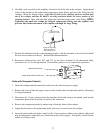
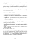
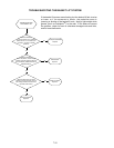
7.4.4 How the Water Heating System Works
To prevent energizing the heating elements when there is no water in the cookpot, these units are
equipped with a low-water-level sensor. This sensor must be grounded by contact with water in the
cookpot before the control circuitry will apply power to the elements. Starch or lime build-up on the
low-water-level sensor may keep the ground from forming, therefore always make sure the sensor is
clean and its lead is firmly connected to J5 on the interface board. In order for the ground to form,
there must be some mineral content in the water (pure water is non-conductive). Consequently, the
units will not operate with distilled water. If distilled, highly filtered, or purified water is used, add
⅛-cup of baking soda to the water each time the cookpot is emptied and refilled.
In addition to the low-water-level sensor discussed above, the water heating system has six more
parts: the high-limit thermostat, the temperature probe, the contactor, the element, and a HEAT
CYCLE switch and manual thermostat, or a computer.
The high-limit thermostat functions as a normally closed switch. If the water in the cookpot falls
below the low-water-level sensor but the sensor remains grounded (for whatever reason), the high-
limit switch will open when the element temperature reaches 400ºF ±15 (204ºC ± 9). This cuts
power to the contactor coil and thus to the element.
The temperature probe is used only when the unit is in the simmer mode. When the operator
selects the simmer mode, logic circuits in the on the interface board or in the computer monitor the
temperature of the water and cycle power to the element (via the contactor coil) on and off as