


7-6
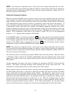
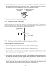
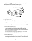
6. Coil the capillary tube as necessary to achieve a neat installation and attach the terminal block to
the mounting bracket using the screws removed in Step 4. Connect thermostat lead 5C (black) to
the normally closed (NC) terminal and 8C (white) to the common (C) terminal.
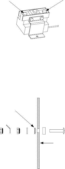
Common (C) Terminal
(Note open side.)
Normally Closed (NC) Terminal
(Note closed side.)
7. Reverse Steps 1 and 2 to complete the procedure.
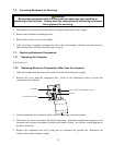
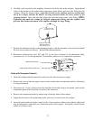
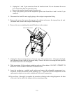
7.3.5 Replacing a Water-Level Sensor
Drain the cookpot and disconnect the cooker from the electrical power supply. Disconnect the
sensor lead from the sensor, remove the nuts securing the sensor in place, and remove the sensor.
Install the replacement sensor as illustrated below and reconnect the lead.
Insulator must seat in
hole before nut is
tightened.
Inside of cookpot.
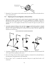
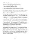
7.3.6 Replacing the Operating Thermostat or Temperature Probe
Units with Manual (Thermostat) Controls
1. Drain the cookpot and disconnect the cooker from the electrical power supply.
2. Disconnect the rocker-switch wires from the terminals of the thermostat body.
3. Loosen the Allen screw in the thermostat control knob and slip the knob off the thermostat shaft.
Remove the two screws securing the thermostat body to the mounting bracket and remove the
thermostat body from the mounting bracket.
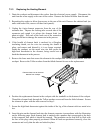
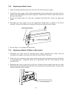
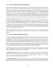
4. At the cookpot, loosen the small nut in the center of the temperature probe fitting, then unscrew
the fitting from the cookpot. Inside the cookpot, remove the probe cover, push the probe out of
its retaining bracket, and withdraw the probe from the cookpot.
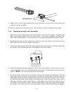
5. Verify that the small nut in the center of the replacement temperature probe fitting is loose and
that the fitting spins easily around the capillary tube. Pass the thermostat bulb through the hole
in the cookpot and position it under the lower portion of the retaining bracket.