


6-10
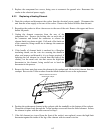
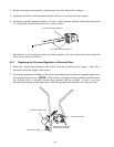
9. Invert the cookpot or rinse tank on a suitable work surface and remove the salvageable
components (e.g., elements, thermostats, drain plumbing, etc.). Install the recovered components
on the replacement cookpot or rinse tank, using thread sealer on all connections.
10. Reverse Steps 1 through 8 to complete the procedure.
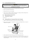
6.4 Troubleshooting
NOTE: 24VAC power to the electronic components of this system is controlled by the master
ON/OFF switch located on the front of the contactor box. If this switch is in the OFF position, none
of the system components will function.
DANGER
The master ON/OFF switch does not disconnect this equipment from the electrical power
source! Line voltage is supplied to the transformer and to the basket lift motors as long as the unit
is plugged in.
Problems with this equipment may be grouped into five broad categories:
1. Failure or malfunction of a 24VAC Power-Supply System component.
2. Failure or malfunction of the Computer.
3. Failure or malfunction of an Autofill/AutoSkim System component.
4. Failure or malfunction of a Water Heating System component.
5. Failure or malfunction of a Basket Lift System component.
Sections 6.4.1 through 6.4.5 briefly explain the functioning of each of the systems mentioned above.
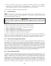
Section 6.4.6 contains troubleshooting guides that provide systematic procedures to isolate and
identify the specific source of a problem. A wiring diagram is located at the end of the chapter.
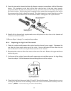
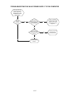
6.4.1 How the Power-Supply System Works
Line voltage is supplied to the system via a power cord that is plugged or hard-wired into the store’s
electrical service. The power cord is attached to a three-lug delta-power terminal block. One set of
wires delivers line voltage from the load side of the block to Terminal 1 of each of the solid-state
relays. A second set of wires delivers line voltage through a pair of 5-Amp fuses to the 24VAC
transformer and to the basket lift relay. Line voltage for one side of the basket lift motor circuit is
tapped from a “piggy-back” terminal on the line side of the transformer. Line voltage for the other
side of the circuit is supplied via the basket lift relay. 24VAC is supplied to the equipment by
placing the master ON/OFF switch in the ON position, which grounds the transformer.
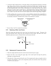
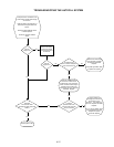
6.4.2 How the Computer Works
The SMS III computer provides the interface between the operator and the system components. The
computer is powered by 24VAC supplied through Pins 1 (hot) and 2 (ground) of the 15-pin wiring
harness. Internal circuitry senses the water level, water temperature, and element temperature.
Depending upon the conditions sensed, the computer energizes or de-energizes the solenoid valve to
control water level and the heating elements to control water temperature. The computer also
controls the lowering and raising of the basket lift, and activates an audible alarm to signal the
operator that a cooking cycle has completed. A rectifier in the computer coverts 24VAC to the