1-9
7. Disconnect the ignition cables from the ignitors by grasping the boots and gently pulling toward
you.
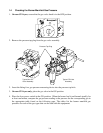
8. Remove the component box mounting screws.
9. Rotate the top of the component box out of the frame and carefully pull it out enough to
disconnect the wiring harness plug(s) from the back of the box.
10. Remove the box and set it aside.
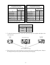
11. Make a note of the location of the existing wires. Using a pin-pusher, disconnect the tempera-
ture probe wires (or high-limit thermostat wires) from the connector plug.
12. Unscrew and remove the temperature probe (or high limit thermostat) from the frypot.
13. Apply Loctite
®
PST56765 pipe thread sealant or equivalent to the replacement part threads.
14. Screw the replacement part into the frypot and torque to 180 inch-pounds.
15. Connect the wires from the new component to the connector plug, referring to the note made in
step 11.
16. Reverse steps 1 through 9 to complete the procedure.
1.6.3 Replacing the Interface Board
1. Remove the component box per steps 1 through 10 of Section 1.6.2.
2. Unplug the controller wiring harness from the interface board.
3. Disconnect the wires attached to the interface board, marking or making a note of the wires and
terminals to facilitate reconnection.
4. Remove the nuts at each corner of the interface board and pull it from the studs.
5. Reverse the procedure to install the replacement board, being sure to reinstall the spacers behind
the interface board.
1.6.4 Replacing an Ignition Module
1. Disconnect the fryer from the electrical supply.
2. Remove the screws from the upper corners of the control panel and swing the panel open from
the top, allowing it to rest on its hinge tabs.
3. Disconnect the wires from the ignition module, marking or making a note of the wires and
terminals to facilitate reconnection.
4. Remove the four ignition module screws and pull the module from the component box.


