1-13
Adjusting Air/Gas Mixture
CE Units Built Through April 1999
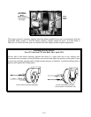
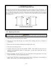
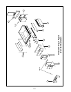
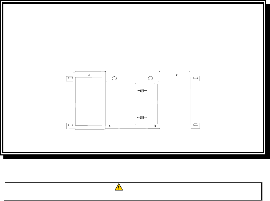
CE units built through April 1999 are equipped with a shield assembly in front of the blowers. An
air shutter plate on the face of the shield assembly regulates the amount of airflow to the blower in-
take. To adjust the shutter plate, loosen the locking screws and slide the shutter to the left or right as
necessary to obtain a bright orange-red glow. Carefully hold the shutter plate in position and tighten
the locking screws.
TYPICAL CE BLOWER SHIELD ASSEMBLY
ON UNITS BUILT THROUGH APRIL 1999
1.6.7 Replacing a Gas Valve
DANGER
Drain the frypot or remove the handle from the drain valve before proceeding further.
1. Disconnect fryer from electrical and gas supplies.
2. Disconnect the wires from the gas valve terminal block, marking each wire to facilitate its
reconnection.
3. Remove the vent tube and the enrichment tube fitting from the valve.
4. Disconnect the flexible gas line(s).
5. Carefully unscrew the valve from the manifold. NOTE: Some models may have the valve
attached to the manifold by means of a pipe union. In such cases, remove the valve by
uncoupling the union.
6. Remove all fittings from the old gas valve and install them on the replacement valve, using
Loctite
®
PST56765 or equivalent pipe thread sealant.
7. Apply Loctite
®
PST 56765 or equivalent pipe thread sealant to the threads of the manifold (or
union). Reverse steps 1-5 to install the replacement gas valve.


