1-32
If power is reaching the motor but the motor fails to run, the motor is burned out and must be
replaced.
ELECTRONICS PROBLEMS
Within this category are problems associated with the relays, microswitches, capacitors, resistors,
interface board, wiring, and controls. The most common problem in this category is a lift that
continuously travels up and down. This is usually caused by a microswitch that is out of adjustment.
Troubleshooting the electronics of either type basket lift is simply a process of verifying current
flow through the individual components up to and including the motor. Using a multimeter set to
the 250 VAC range, check the connections on both sides of the component for the presence of the
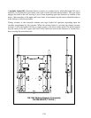
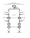
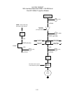
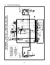
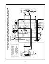
applied line voltage. The accompanying simplified wiring diagrams identify the components and
wiring connection points.
1.7.8 Interpretation of Digital Controller Lights
Power light on, heat light cycling, trouble light off, and melt light on:
● If fryer oil temperature is below 180ºF (82ºC), the lights indicate the unit is operating
normally.
● If the oil temperature is above 180ºF (82ºC) and the heat light continues to cycle as if in the
melt cycle, this may indicate a defective probe circuit or low incoming 12VAC to the
controller.
Power light on, heat light on, trouble light off, and melt light off:
● If the fryer oil temperature is above 180ºF (82ºC) and below the setpoint temperature, the
lights indicate the unit is operating properly.
● If the oil temperature is above the temperature set on the control knob and the heat light
remains lit, this may indicate a defective probe circuit.
Power light on, heat light off, trouble light on, and melt light off:
● If the fryer oil temperature is below 410ºF (210ºC), the lights indicate one of the following:
a. The probe circuit is defective, or
b. There is a connection problem on pins 2 or 10 on the 15-pin wiring harness.
● If the fryer oil temperature is above 410ºF (210ºC), the lights indicate a run-away heating
circuit.
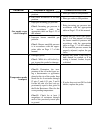
1.8 Troubleshooting Guide
The troubleshooting guide that follows is intended to assist service technicians in quickly isolating
the probable causes of equipment malfunctions. An additional set of operator troubleshooting guides
is contained in Chapter 6 of the H50 Series Installation and Operation Manual (P/N 819-5000). It is
suggested that service technicians thoroughly familiarize themselves with both sets.


