Page 64
Part # MCOSM06 Rev 1 (11/03/08)
GENERAL TROUBLE SHOOTING GUIDE
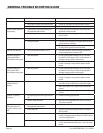
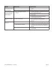
Problem Possible Cause Corrective Action
Fan will not run A. No Power to Unit A. Turn Power on
B. No power to motor from relay board B. Check for voltage from relay board to motor
C. Micro Switch Not closing C. Check micro switches
Button on key pad not
responding
A. Loose ribbon connection between
key pad and smart board
A. Check that ribbon connection from key pad is
attached to smart board
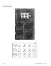
B. Faulty key pad B. Refer to key pad testing procedure on bulletin
#B-107-2001
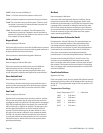
'Prob' in display A. Probe disconnected A. Reattach probe
B. Probe has failed B. Conrm ohm resistance of probe. Refer to cavity
probe chart for readings.
C. Check for continuity between probe connection
at relay board, probe harness & probe
Unit will not shut o A. Cavity temperature above 150°F A. Normal operation. Unit will not go to O until
cavity temperature is below 150°F
No HIGH speed but
HIGH speed LED is
illuminated on key pad
A. Bad relay board A. CR3 on relay board should be on, if not check
for 24VDC ±10% at pins 5 & 7 at relay board. If
voltage present replace relay board
B. Bad smart board B. Check for 24VDC ±10% at pins 5 & 7 at relay
board. If voltage is not present replace smart
board
No LOW speed but
LOW speed LED is
illuminated on key pad
A. Bad relay board A. CR4 on relay board should be on, if not check
for 24VDC ±10% at pins 5 & 8 at relay board. If
voltage present replace relay board
B. Bad smart board B. Check for 24VDC ±10% at pins 5 & 8 at relay
board. If voltage is not present replace smart
board
Unit will not heat.
DOOR shown in
display
A. Open circuit on upper door switch A. Unplug unit from supply. With door closed
between NO and COM switch should be open.
B. With door open to 30° angle switch should be
closed
C. With door open all the way switch should be
closed.
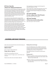
Ignition - Lighting
problems
A. Incorrect gas pressure or gas turned
o
A. Check incoming gas pressure
B. Various faults possible B. Refer to trial and ignition ow chart in Section
Two of this manual
Unit will not turn
ON when button is
pushed, display reads
OFF
A. Loose ribbon connection between
key pad and smart board
A. Check connection
B. Faulty key pad B. Refer to key pad testing procedure on bulletin
#B-107-2001
No Display A. No power to smart board A. Check for 24 VAC between pins 1 and 3 on smart
board. If voltage present check for 24 VAC at pins
1 and 3 at relay board.
B. No power to relay board B. Check for 24 VAC into relay board and 24 VAC
out of relay board between pins 1 and 3 on relay
board


