03/09/09 P/N 4523367 Page 20
23) Attach Bracket to Oven
For Standard Ovens:
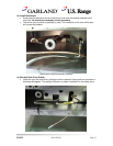
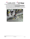
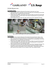
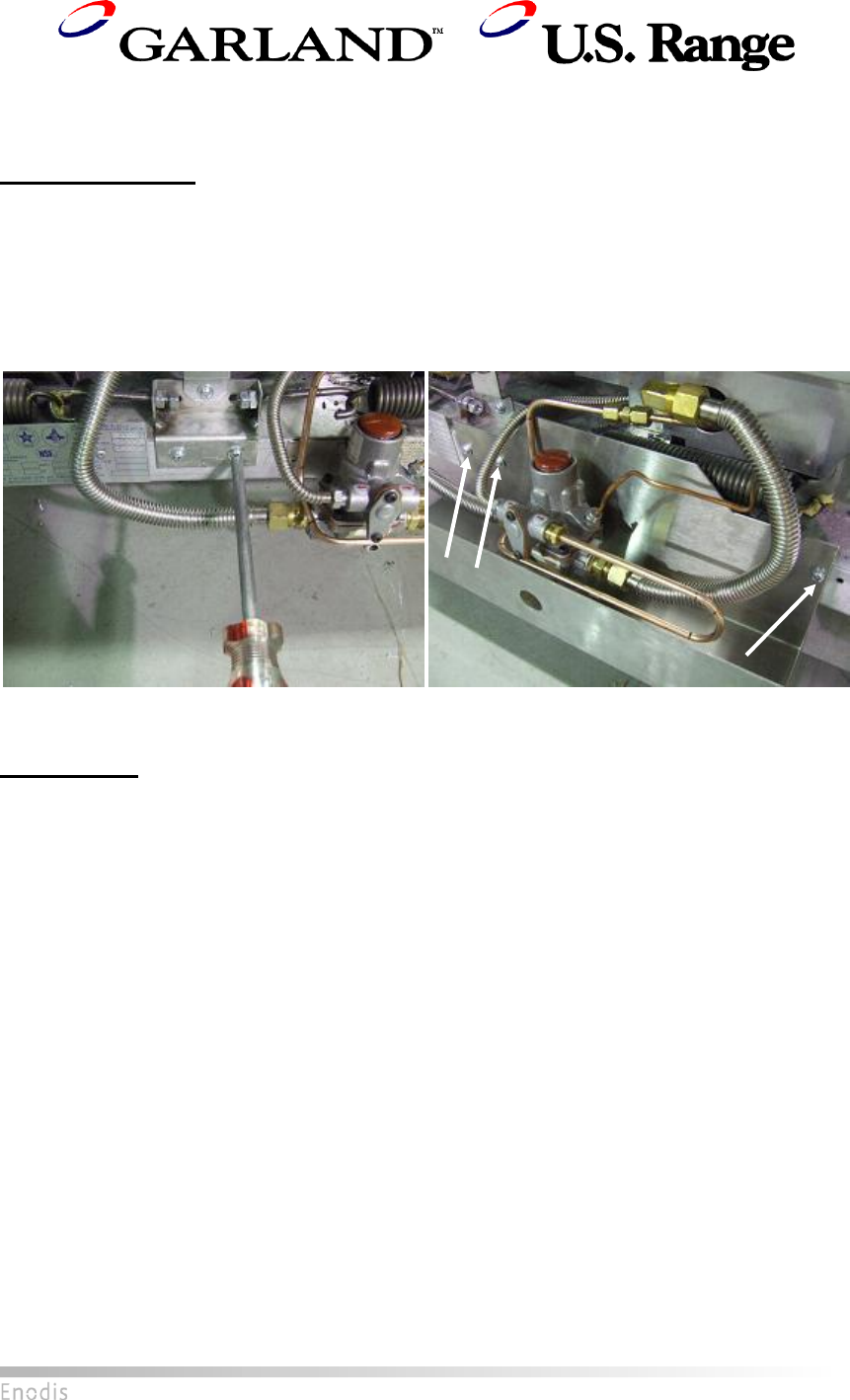
Unscrew the two screws holding the orifice bracket to the lower oven frame.
Slip the bracket (Part 8, Assembly Drawing) underneath the valve assembly such that the
taller face is flush up against the lower oven frame.
Position the screw holes on the bracket such that two of them line up with the holes used
for the orifice bracket. The third hole on the far right of the bracket will line up with a hole
on the lower oven frame.
Screw bracket onto oven frame with sheet metal screws (Part 9, Assembly Drawing).
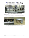
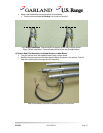
Left: Unscrewing two lower screws of orifice bracket
Right: Attached valve bracket with arrows indicating location of screws
For RC Ovens:
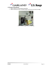
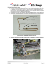
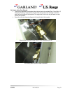
Unscrew the two screws holding the orifice bracket and the piezoelectric lighter to the
lower oven frame. Unscrew the left screw on the right side bell crank assembly bracket.
Slip the bracket (Part 8, Assembly Drawing) underneath the valve assembly such that the
taller face is flush up against the lower oven frame.
Position the screw holes on the bracket such that two of them line up with the holes used
for the orifice bracket. The third hole on the far right of the bracket will line up the hole
used on the right side bell crank assembly bracket.
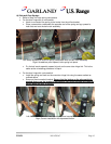
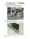
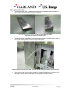
Screw bracket onto oven frame with sheet metal screws (Part 9, Assembly Drawing). The
two screws on the left side of the bracket should go through the piezoelectric lighter
bracket first, then the valve bracket, then the orifice bracket. The right side screw should
go through the valve bracket first, then through the bell crank assembly bracket.


