


Part # P157 Rev 2(01/06/10) Page 7
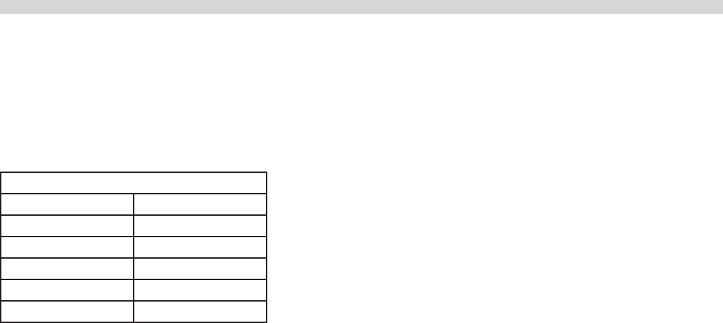
Clearances
The space in which the appliance is to be sited must include
the minimum installation clearances to combustible surfaces
as indicated in the following table.
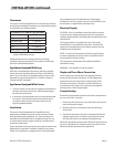
CLEARANCE TO COMBUSTIBLE MATERIAL
Location All Models
Top *
Left Hand Side 1” (25mm)
Right Hand Side 1” (25mm)
Rear 1.5” (38mm)
Type of Floor or Base Combustible
* NOTE Equipment must be installed
under a ventilation canopy
Adequate clearance must be provided for servicing,
ventilation & proper operation. The product must be kept
free from combustible material.
Appliances Equipped With Legs
All Fryers are shipped from the factory with legs installed
unless otherwise specied. When the fryer is specied for
dais or cove mounting it is shipped less legs. Legs must be
adjusted to a minimum height of 6” (152mm) in order to
comply with NSF standards.
Appliances Equipped With Casters
1. The front casters on the unit are equipped with brakes to
limit the movement of the fryer without depending on
the electrical connection.
2. A restraint can be attached to the unit near the electrical
connection. If the restraint is disconnected be sure to
reconnect it after the fryer has been returned to its
original installed position.
Ventilation
The area in which the appliance is installed must be
adequately ventilated to provide air for removal of steam,
heat generated by the appliance, etc. These products are
intended to be installed under a ventilation hood. The use
of a mechanical extract system should be considered and
conform to local codes.
Proper operation of exhaust fans (proper speed, rotation and
adjustment) is essential. In addition a make-up air system
(HVAC) for the kitchen to supply fresh air is recommended.
Any ventilation system will break down if improperly
maintained. The duct system, the hood, and the lters must
be cleaned on a regular bases and kept clean.
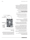
Electrical Supply
CAUTION: Prior to installation check the electrical supply
to ensure input voltage and phase match the equipment
voltage rating and phase. See data plate located inside of the
cabinet door.
The supply entrance is located at the rear. The supply
terminal block is accessible from the front. The electrical
supply must be adequate for the voltage, phase & current
marked on the rating plate.
NOTE: A means of disconnection from the supply having
a contact separation of at least 3 mm in all poles must be
incorporated in the xed wiring.
This equipment is intended to be installed with xed
permanent wiring
WARNING: This appliance must be earthed.
Single and Three Phase Connection
Unless otherwise noted all fryers are shipped from the
factory for three phase connection. A wiring diagram is
attached to the rear of each fryer. Visually check all the
electrical connections. The fryer is wired at the factory
as specied on the order. If it is necessary to change the
phasing, refer to the wiring diagram.
Commissioning
Ensure all circuit breakers located in the lower compartment
are set to the ‘ON’ (1) position.
1. Ensure that all controls are in the o position and turn on
the main electrical supply.
2. Operate the fryer in accordance with the operating
instructions.
3. Check that the product functions correctly and that the
voltage supply to the unit does not drop by more than
5% when all sections are operated simultaneously.
When the operation has been check, hand the instructions to
the user or purchaser for retention and instruct them in the
ecient and safe operation of the appliance.
INSTALLATION continued