


Part # 4517957 Rev. 13 (02/10/11)Page 14
MAINTENANCE & CLEANING continued
Convection Oven
1. Open the lower kick panel.
2. Remove the left & right hand oven door springs. USE
CAUTION: the oven door will need additional support to
remain closed.
3. Remove the left and right hand radiation shields.
4. Remove the two (2) screws that secure the pilot bracket
and disconnect the pilot tubing at the union connection.
5. Remove the injector support and slide the burner and
burner pan forwards out of the combustion chamber.
6. Clean the burner with a sti scrubbing brush and shake
the burner well to ensure that ports are clear of any
debris.
7. Reassemble in the reverse order.
Pilot Burner Cleaning
1. Remove the main burners (refer to the section on main
burner cleaning).
2. Disconnect the pilot gas supply pipe from the pilot jet.
3. Remove the pilot jet.
4. Clean by blowing through or washing. Do not use wire to
clear the pilot jet.
5. Reassemble in the reverse order.
Gas Valve
Re-greasing of the gas taps is not recommended. If the
tap spindle becomes seized or dicult to turn, refer to
Replacement of Parts section in this manual.
Thermostat Calibration
Oven
It is normal for a hydraulic thermostat cycling with a
temperature dierential of 45° to 50°F. If the thermostat
is cycling beyond the 15° tolerance above or below the
set point and the appliance is under warranty, recalibrate
the thermostat or if not under warranty, consult owner for
proper action. If the thermostat is out of calibration more
than 50°, it will not likely hold an attempt of recalibration. We
suggest that the thermostat be replaced.
1. Place the thermocouple of the test instrument in the
center of the oven.
2. Turn the oven temperature control dial to 400°F. In order
to allow the oven temperature to stabilize, the oven
control must be allowed to cycle twice before taking a
test reading.
3. Check the temperature reading just when the control
cycles “OFF” as indicated by cycling pilot lamp. If the
temperature does not read within 15°F of the dial setting,
recalibrate as follows:
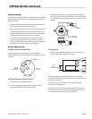
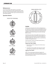
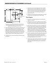
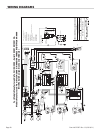
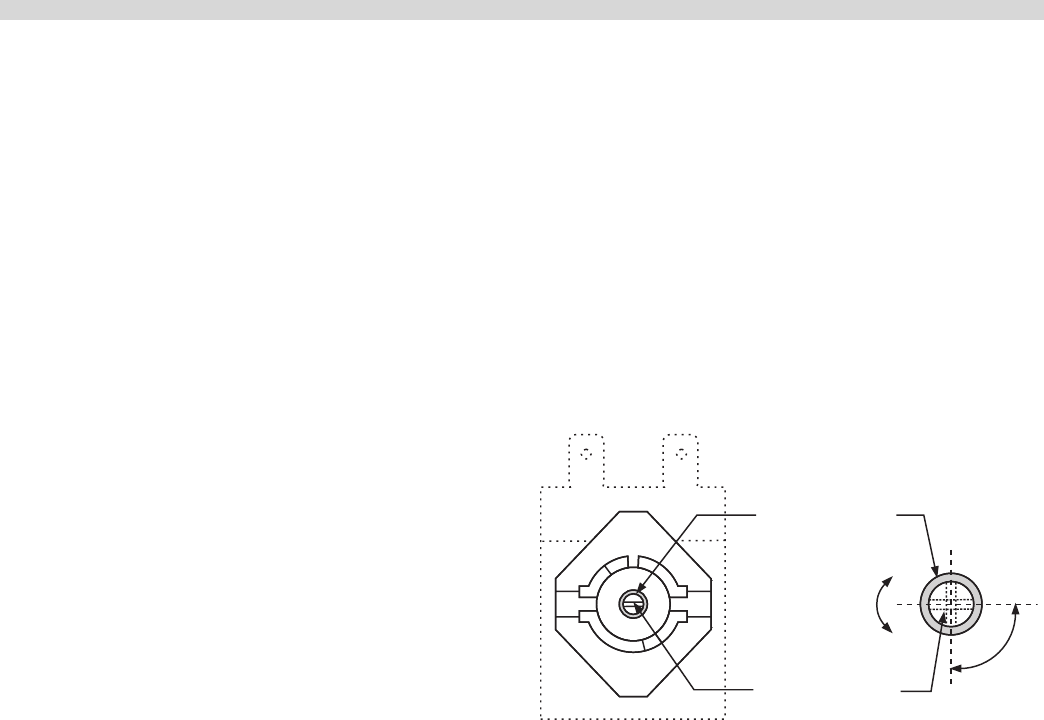
4. Carefully remove the thermostat dial, not disturbing the
dial setting.
Decrease
Increase
"A" Calibration
Screw Head
"B" Dial Shaft
1/4
Turn
5. Hold the thermostat shaft steady and with a small at
blade screw driver, turn the calibration screw located
inside the shaft clockwise to decrease the temperature
and anti-clockwise to increase the temperature. Note:
Each 1/4 turn of the screw will create a change of
approximately 25°F.
6. Replace the thermostat dial and repeat steps 1 through 3
to verify that correct adjustment has been made.
Griddle
1. Use a test instrument with a special disc type
thermocouple or a reliable surface type pyrometer. Note:
a drop of oil on the face of the disc will provide better
contact with the plate.
2. Set all griddle thermostats to 300°F. In order to allow the
griddle temperature to stabilize, the thermostats must be
allowed to cycle twice before taking a test reading.