


Part # 4517957 Rev. 13 (02/10/11)Page 8
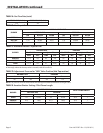
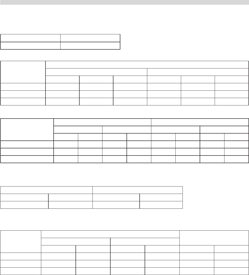
TABLE A. Gas Flow Rate (total)
NATURAL GAS ( ft
3
/h ) PROPANE GAS (ft
3
/h )
113 42
TABLE B. Heat Input Per Burner
BURNER
NOMINAL HEAT INPUT
NATURAL GAS PROPANE
kW BTU/HR MJ/HR kW BTU/HR MJ/HR
GRIDDLE 7.32 25,000 26.37 7.32 25,000 26.37
HOT TOP 7.32 25,000 26.37 7.32 25,000 26.37
OVEN 11.14 38,000 40.08 8.79 30,000 31.65
TABLE C. Manifold Pressure / Injector Size
BURNER
NATURAL GAS PROPANE
Manifold Pressure Injector Size Manifold Pressure Injector Size
mbar "W.C. DMS mm mbar "W.C. DMS mm
GRIDDLE 11.2 4.5 42 2.4 25 10 53 1.51
HOT TOP 11.2 4.5 41 2.45 25 10 — 1.5
OVEN 11.2 4.5 31 3.05 25 10 51 1.7
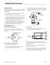
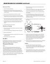
NOTE: The pressure must be measured at the pressure test nipple located on the main manifold, located at the left hand front
of the range where the hot top valve is situated, with all burners lit.
TABLE D. Adjustment Pressure for “MIN” Valve Position (Hot Top section)
NATURAL GAS PROPANE
mbar "w.c. mbar "w.c.
2.0 0.8 4.5 1.8
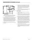
NOTE: The pressure must be measured at the test nipple located downstream of the gas valve.
TABLE E. Aeration Shutter Setting / Pilot Flame Length
BURNER
SHUTTER OPENING
PILOT FLAME LENGTH
NATURAL GAS PROPANE
mm Ins. mm Ins. mm Ins.
OVEN 19 0.750 19 0.750 25.4 1
GRIDDLE 41.3 1.625 41.3 1.625 25.4 1
HOT TOP 41.3 1.625 41.3 1.625 12.5 0.5
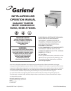
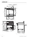
INSTALLATION continued