


32
a
b
e
f
c
d
1
2
�
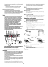
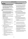
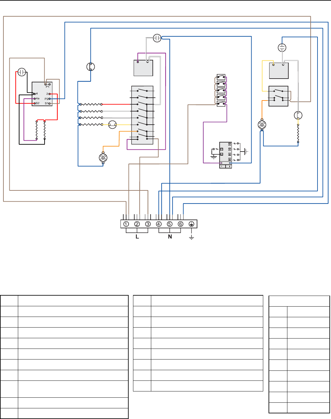
Key
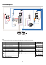
The connections shown in the circuit diagram are for single-phase. The ratings are for 230V 50Hz.
Colour Code
b Blue
br Brown
bk Black
or Orange
r Red
v Violet
w White
y Yellow
g/y Green/yellow
gr Grey
Circuit Diagram
Code Description
A1 Grill control
A2 Grill element left-hand side
A3 Grill element right-hand side
B1 Left-hand MF oven thermostat
B2 Left-hand MF oven function control
B3 Left-hand MF oven base element
B4 Left-hand MF oven top element (outer pair)
B5
Left-hand MF oven browning element (inner
pair)
B6 Left-hand MF oven fan element
B7 Left-hand MF oven fan
Code Description
C1 Right-hand fan oven thermostat
C2 Right-hand fan oven control
C3 Right-hand fan oven element
C4 Right-hand fan oven fan
D Thermal cut-out
F Neon
G1 Ignition switch
G2 Ignition spark generator