


BEFORE YOU BEGIN
Read these instructions completely and
carefu~y
~ORT~:
Save these instructions for the
Iocd
electrid
inspectors use.
WORTM:
Observed governing codes
and ordinances.
NOTE TO
~~~~
be
these
instructions with the
appfiance
after
ins~tion
is completed.
N~
~
CONS~R
&ep
this Use and
We
Guide and
kstiation
kstructions
for
fiture
use.
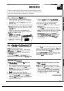
ELECTRIU
REQUIREMENTS
This
appfiance maybe
connected by
mems
of
permanent
“hard
wirin<
or power supply
cord
kit
It
is
the personal responsibtity of the customer
to contact a
qu~ed
technician to assure that
the
electrid
initiation is adequate and is in
conformance
with
the National Electrical Code
and
10A
codes and ordinances.
~E
WGE
MUST BE
CONNE~D
=
COPPER=
ONLY. Numinum wire must
not be used to avoid
potentidy
msatisfactory
connections.
POWER SUPPLY CORD
WT
This
app~ance
maybe connected by means of a
power supply cord kit.
Ordy
a power supply cord
kit rated at 125/250 volts
minimum, 40
amps
and marked for use with ranges
shd
be
used. Cord must have 3 conductors,
Mobtie
home initiation or area where
lod
codes do not permit grounding through
neuti,
a 4 conductor power
supp~
cord kit rated at
125/250
VOltS
minimum, 40
=PS
and
marked for use with ranges
sh~
be used.
Terminals on end of wires must be either closed
loop or
open+nd spade lugs with upturned ends.
Cord must have strain
rehef
cbp.
MODEM WITH
FA~ORY
CONNE~ED
POWER SUPPLY CORD
Some models may be equipped with a factory
connected 3 conductor power supply cord.
Mobfle
home initiation or area where local
codes do not permit grounding through neutral,
a 4 conductor power supply cord kit rated at
125/250
VOltS
minimum, 40
=PS
and
investigated for use with ranges
shd
be used.
Terrninds
on end of wires must be either closed
loop or
open+nd spade lugs with upturned ends.
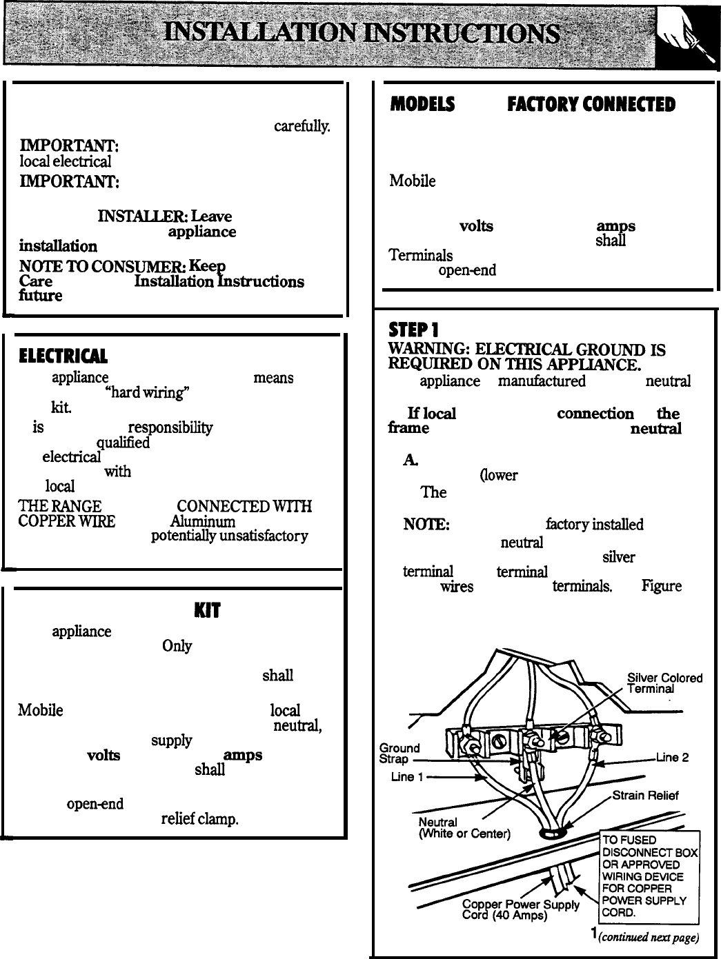
This
apptiance
is
mandctured
with the
neuti
terminal connected to the frame.
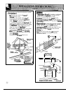
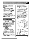
1.
Uld
codes permit
connetion
of
tie
tie
grounding conductor to the
neuti
wire of the copper power supply cord:
A
Remove the screws and raise the terminal
block cover
~ower
part of the back wire cover).
B.
me
terminal nuts are taped to the frame
below the terminal block
N~:
Do not loosen
bctoryinstied
nuts.
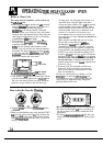
C. Connect the
neuti
wire of the copper
power supply cord to the center
sflver
colored
teti
of the
teti
block and connect the
outer
ties
to the outer
tetis.
See
Piie
1.
Ring type terminals must be used on copper
power supply cord wires.
D.
Replace the terminal block cover.
FIGURE
l(conttimpage)
31