


me
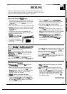
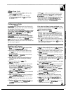
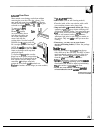
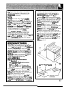
figure below shows the recommended
initiation relationship of the ranges to the
vertid
wds
of the surrounding structure.
Please note the following:
N~:
1.
The
back of the range maybe
instiled
directiy
against the rear
WW
of the structure.
2.
~ese
ranges conform to
W
requirements for
“O”
spacing from the range to adjacent
vertid
WWS
above the countertop level. However, to
reduce possible scorching
ofvertid
wds
and to
~
potential
tie
h-ds
under
abnoti
surface unit use conditions such as high heat or
no pans, a minimum of 2“ spacing should be
provided on both sides of the
cooktop.
3. To
etiate
the
h-d
of reaching over
heated surface units, cabinet storage space
located above the surface units should be
avoided.
E
a cabinet is to be provided, the
hwd
a
be reduced by
ins-g
a range hood that
projects
hotiontiy
a
minimum of 5“ beyond
the bottom of the cabinets.
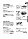
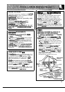
IMMRTUT
WEm
WMNIHG
This range
must be properly secured to the
floor by using the included anti-tip
brackek
and
screws.
Fdure
to
insti
the brackets
cotid
~ow
the range to
accidentiy
tip over if excessive
weight is placed on an open door or if a
ctid
chbs
upon it. Serious injury might result from
spfled hot
Equids
or from the range
itse~.
Refer
to the instructions below for proper
ks~tion.
N~:
E
the range is ever moved to a different
location, the anti-tip brackets must
dso
be
moved and
kstied
with the range.
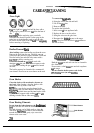
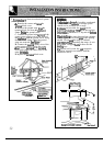
~-~
BRAC~
~STUnON
~~U~ONS
Tools
Rqtied:
5/16”
Nutdriver
or
Nat
Head Screwdriver
Adjustable Wrench
3/8”
Electric
Dfl
& 3/16” Diameter Bit
3/16” Diameter Masonry
Dfl
(ifins~g
in concrete)
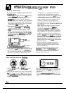
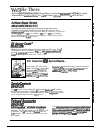
Brackets
a~ch
to the floor at the back of
tie
range
to hold
boti
rear leg levelers. When fastening to
tie
floor, be sure that screws do not penetrate
electrid
wiring or plumbing. The screws provided
d
work in either wood or concrete.
1.
Unfold the paper template and
pb
it
fit
on
tie
floor with the back and side edges positioned
-y
where the back and sides of the range
W
be
lomted
when
instied.
~se
the diagram to
l~te
the brackets
tithe
tempbte is not
a~ble.)
2. Mark on the floor the location of the 4
nounting holes shown on the
tempkte.
For
:asier
ins~ation,
3/16” diameter
pflot
holes,
1/2” deep
m
be
~ed
into the
floor.
3. Remove
tie
template and place the brackets
)n
the floor with turned up flanges to the
tiont
tie
up the holes in the brackets with marks on
he floor and attach with the 4 screws provided.
3rackets
must be secured to a
sohd
floor.
U
lttaching
to masonry floor, first
dfl
3/16”
tiameter
pflot
holes using a concrete bit
t.
hvel
the range if necessary, by adjusting the
I
leg levelers with a wrench. @minimum
:learance
of 1/8” is required between the bottom
}f
the range and the rear
levekg
feet)
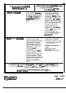
j.
Shale the range into place making sure the
ear legs are trapped by the ends of the brackets.
%e
range may need to be shifted
stighfly
to one
ideas it is being pushed back to
dow
the rear
sgs
to
dgn
with the brackets. Remove the
torage drawer to inspect brackets or grasp the
Bp
rear edge of the range and
wefu~y
attempt
~
tit
it forward to make sure the range is
Iroper&
anchored.
Bd
Edge of
Rmge
or Re~
WAI
I
I
33