


❑
MTFTIPDMCE
lH=~lON
lN~U~lONS
N~:
A risk of range
tip-ver
~sts
if the
appfiance
is not
instied
in accordance with the
initiation instructions provided.
me
proper
use of this device
~es
the risk of
~P-
O~R
In using this
detice
tie
consumer must
sti~
observe the safety instructions as stated in
the USE and
Cm
GU~E
and avoid
uskg
the
oven door and/or lower drawer as a step stool.
hstilation
instructions are provided for wood
and cement in
eitier
floor or
wW.
Any other
m
of construction may require special
ins~tion
techniques as deemed necessary to provide
adequate fastening of the
AN~-TF
bracket to
the floor or
wd.
Ethe
anti-tip device supptied
with
the range does not fit this application, use
the universal anti-tip device
WB02X7909.
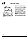
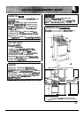
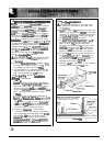
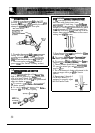
Step
l—bca~
tie
Bracket
A
Mark the floor or
~
where either the right
or left ‘EDGE” of the
20inch
opening is to
be
loated.
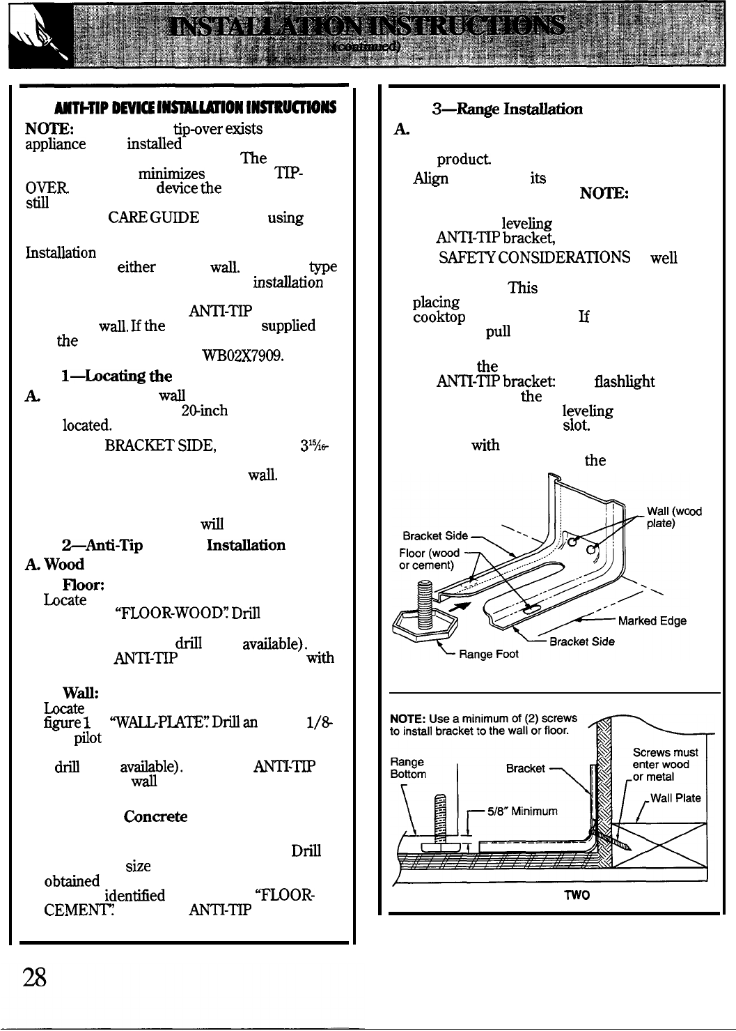
B. Place the
BWC=
S~E,
see figure 1,
31%*
inch from the marked “EDGE” toward center
of opening and against the back
wW.
C. Use the bracket as a template and mark the
required holes, as shown in figure 1, for the
type of construction you
~
be using.
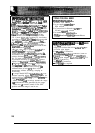
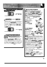
Step
>Anti-Tip
Bracket
Ins*tion
A
Woti
Construction:
1.
moor:
bcate
the center of the 2 holes identified in
figure 1 as
“F~OR-WOOD~
Dfl
a l/&inch
pilot hole in the center of each hole (a nail or
awl may be used if a
til
is not
av~ble).
Secure the
AN~-~
bracket to the floor
witi
the 2 screws provided. Proceed to Step 3.
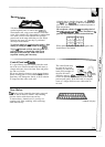
2.
Wd:
tite
the
center of the 2 holes identified in
-e
1
as
W_P~~’~Dflan
angled
1/8
inch
pflot
hole in the center of each hole as
shown in&e 2. (And or awl maybe used if
a
~
is not
avfible).
Secure the
~-~
bracket to the
ti
with the 2 screws provided
as shown in figure 2. Proceed to Step 3.
B. Cement or
Con-te
Construction:
1. Suitable screws for concrete construction
can be obtained at the hardware store.
Dri~
the required
she
hole for the hardware
obtied
into the concrete at the center of
the holes
identied
in figure 1 as
‘F~OR-
CEME~~
Secure the
AN~-~P
bracket to
the floor. Proceed to Step 3.
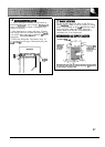
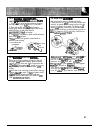
Step
3—~e
InsMation
A
Complete the initiation of the range per
the initiation instructions provided with
the
produti
B.
~gn
the range to
ik
designated location and
shale it back into position.
N~:
A minimum
clearance of 5/&inch is required between the
range and the
levehg
foot that will engage
the
AN~-~P
bracket
see figure 2.
C. For
SAF~
CONSIDEW~ONS
as we~ as
optimum performance adjust the range so
that it is level.
~is
maybe checked by
phcing
a level or a large pan of water on the
cooktop or the oven rack.
U
an adjustment
is required
pun the range forward, tip the
range and rotate the level feet as required.
D. To check
tie
range for proper instigation of
the
AN~-~P
bracket
use a
flashkht
and
look underneath
tie
bottom of the range to
see that one of the rear
IeveMg legs is
engaged in the bracket
slot
E. Proceed
witi
the remainder of the initiation
instructions provided with
the range.
d
FIGURE ONE
FIGURE
WO