


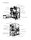
16
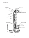
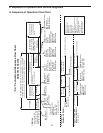
12) Drain Cycle–"FLUSH" (drain) LED is on. IMPORTANT! Drain valve will not energize
unless the safety switch is engaged. The appliance is factory set to drain the
evaporator and reservoir once every hour for 2 seconds. A manual drain is provided
when cleaning the appliance by moving the control switch from the "ICE" position to the
"DRAIN" position. A 1-in-12 drain cycle is also available. For further details, see "III.C. 3.
Drain Frequency Control (S1 dip switch 4)."
a) Automatic Drain Cycle: A drain cycle occurs once every hour for 2seconds.
DCTterminates and DVT starts. Once DVT terminates, DCTresets and DV
de-energizes. DCT resets every time the power supply is turned off and on again.
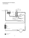
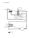
Diagnosis: Once DCT terminates, DV energizes. If not, check for 24VAC from
K2connector pin #10 (W/BU) to a neutral (LBU). If 24VAC is not present, replace CB.
If 24VAC is present, check for 24VAC at DV. If 24VAC is present and DV does not
energize, check DV solenoid continuity.
b) Manual Drain: Move control switch to the "OFF" position, pause momentarily, then
move to the "DRAIN" position. DV energizes.
DV continues until control switch is moved to "OFF" or "ICE" position or power is
turned off.
Note: a) A momentary pause in the "OFF" position is necessary to de-energize the
control board when moving the control switch between "ICE" and "DRAIN."
Otherwise there is a delay of several minutes before the new selection takes
effect.
b) If the control switch is left in the "DRAIN" position for 10 minutes or more, a
2-beep alarm sounds every 5 seconds. Move the control switch out of the
"DRAIN" position to clear the alarm.
Diagnosis: DV energizes. If not, check for 24VAC at CBK2connector pin
#10(W/BU) to a neutral (LBU). If 24VAC is not present, conrm 24VAC power
supply to CB K2connector pin #9(W/R) to a neutral (LBU). If 24VAC is present on
CB K2 connector pin #9(W/R) and not on CB K2 connector pin #10(W/BU), check
for 5VDC at CB K9 connector pin #1 (W/BK) to CBred K4 connector pin closest to
CBblack K3connector. If 5VDC is not present on CB K9 connector pin #1 (W/BK),
replace CB. If 5VDC is present on CB K9 connector pin #1 (W/BK), check for 5VDC
at CB K9 connector pin #2 (W/BK) to CBred K4 connector pin closest to CBblack
K3connector. If 5VDC is not present on pin #2 (W/BK), check continuity of control
switch. If open, place in "DRAIN" position or replace control switch.
If 24VAC is present at CB K2 connector pin #10 (W/BU), check for 24VAC at DV. If
24VAC is present and DV does not energize, check DV solenoid continuity.