


47
16) Evacuate the system, and charge it with refrigerant. See the nameplate for the required
refrigerant charge.
17) Install the new auger assembly with the upper part of the mechanical seal attached.
Secure the auger assembly using new allen head cap screws.
18) Replace the evaporator bracket and reconnect the water hoses.
19) Replace spout A, spout B, and the storage bin cover in their correct positions.
20) Move the power switch to the "ON" position, then replace the panels in their correct
positions.
21) Turn on the power supply, then move the control switch to the "ICE" position to start the
automatic icemaking process.
5. Removal and Replacement of Mechanical Seal and Lower Housing
5a. Mechanical Seal
1) Move the control switch to the "DRAIN" position and drain all of the water from the
evaporator.
2) After the water has stopped draining, move the control switch to the "OFF" position, then
turn off the power supply. Remove the front and top panels, then move the power switch
to the "OFF" position.
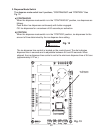
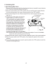
3) Remove storage bin cover. Remove spout B, then remove spout A. See Fig. 14.
4) Remove the apron panel, then remove the left side panel.
5) Remove the extruding head heater and the allen head cap screws securing the
extruding head and discard the allen head cap screws.
6) Using the cutter, lift out the auger assembly, then remove the evaporator bracket.
7) The mechanical seal consists of two parts. One moves along with the auger, and the
other is xed on the lower housing. NOTICE! If the contact surfaces of these two
parts are worn, cracked, or scratched, the mechanical seal may cause water leaks
and should be replaced.
8) Remove the allen head cap screws securing the evaporator to the lower housing.
9) Raise the evaporator up to access the lower housing.
10) Remove the mechanical seal from the housing. If only replacing the mechanical seal,
proceed to step 13. NOTICE! To help prevent water leaks, be careful not to damage
the surfaces of the O-ring or mechanical seal.
5b. Lower Housing
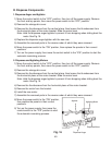
11) Remove the O-ring and the bolts securing the housing to the gear motor and remove
the housing from the gear motor. If inspection of the upper bearing inside the extruding
head (see "IV.C.1. Upper Bearing Wear Check") indicates that it is out of tolerance,
replace both it and the bearing inside the lower housing.
Note: Replacing the bearing requires a bearing press adaptor. If one is not available,
replace the whole extruding head and housing.
12) Install the O-ring and mount the lower housing on the gear motor.