


23
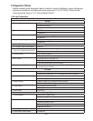
• Ice Dispense Switch/Ice Dispense Sensor:
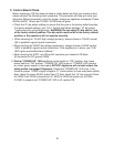
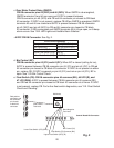
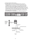
h. Push Button Model–"ICE" and "AM" LEDs are on: Before engaging the
ice dispense switch, check for the correct VDC from the locations given in the
"Disengaged" column in the table below. If the VDC is different than in the table,
replace CB. If the VDC is correct, engage the ice dispense switch. "ICE" LED
turns on. If not, conrm position of dispense mode switch and that the portion and
continuous VDC matches the "Engaged" column in the table below. If not, check the
ice dispense switch continuity when engaged (closed) and the dispense mode switch
continuity. If dispense switch is open when engaged, replace. If dispense mode
switch is open, replace. If the VDC matches the "Engaged" column below and the
"ICE" LED does not turn on, replace CB.
Note: "AM" LED turns on .6 sec. for every 12 sec. of cumulative dispense time.
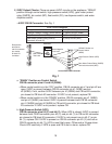
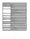
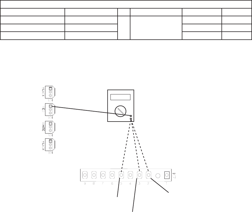
5VDC CB K7 Connector
Component Pin # (Wire Color) To CB VDC Ground Disengaged Engaged
Portion Signal #5 (R)
To
Red K4 pin closest
to black K3
0VDC 5VDC
5VDC Power Supply #3 (BR) 5VDC 5VDC
Continuous Signal #2 (Y) 0VDC 5VDC
Red positive
test lead to red
K4 connector
pin closest
to black K3
connector
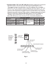
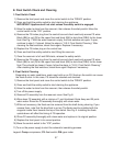
Fig. 5
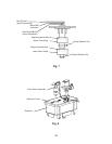
Red Positive
Test Lead
Black Negative
Test Lead
Multimeter
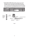
5VDC
Control Board K7 Connector
Ice Dispense (R)
(portion signal)
Ice Dispense (BR)
(5VDC power supply)
Ice Dispense (Y)
(continuous signal)