


3
IMPORTANT
This manual should be read carefully before the appliance is serviced. Read
the warnings and guidelines contained in this manual carefully as they provide
essential information for the continued safe use, service, and maintenance of the
appliance. Retain this manual for any further reference that may be necessary.
CONTENTS
Important Safety Information ................................................................................................. 5
I. Construction and Water/Refrigeration Circuit Diagrams ..................................................... 7
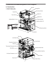
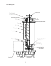
A. Construction .................................................................................................................. 7
1. DCM-751BAH(-OS) .................................................................................................. 7
2. DCM-751BWH(-OS) ................................................................................................ 8
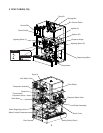
3. Ice Making Unit ........................................................................................................ 9
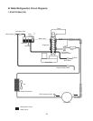
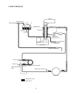
B. Water/Refrigeration Circuit Diagrams .......................................................................... 10
1. DCM-751BAH(-OS) ................................................................................................ 10
2. DCM-751BWH(-OS) ..............................................................................................11
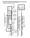
II. Sequence of Operation and Service Diagnosis ............................................................... 12
A. Sequence of Operation Flow Chart ............................................................................. 12
B. Service Diagnosis ....................................................................................................... 13
C. Control Board Check ................................................................................................... 18
D. Bin Control Check ....................................................................................................... 26
E. Float Switch Check and Cleaning ............................................................................... 27
F. Diagnostic Tables ......................................................................................................... 29
1. No Ice Production ................................................................................................... 29
2. Ice/Water Dispensing ............................................................................................. 31
III. Controls and Adjustments ............................................................................................... 32
A. Control Board Layout .................................................................................................. 33
1. DCM-751B_H ......................................................................................................... 33
2. DCM-751B_H-OS .................................................................................................. 34
B. LED Lights and Audible Alarm Safeties ....................................................................... 35
C. Settings and Adjustments ............................................................................................ 36
1. Default Dip Switch Settings .................................................................................... 36
2. Infrared Sensor Shutdown Delay (S1 dip switch 1, 2, 3) ....................................... 36
3. Drain Frequency Control (S1 dip switch 4) ............................................................ 36
4. Continuous Dispensing Timer (S1 dip switch 5 & 6) .............................................. 37
5. Bin Control Selector (S1 dip switch 7) ................................................................... 37
6. Bin Control Shutdown Delay (S1 dip switch 8) ...................................................... 37
7. Factory Use (S1 Dip Switch 9 & 10) ....................................................................... 37
D. Power Switch, Control Switch, and Dispense Mode Switch ....................................... 38
IV. Removal and Replacement of Components ................................................................... 40
A. Service for Refrigerant Lines ....................................................................................... 40
1. Refrigerant Recovery ............................................................................................. 41
2. Brazing .................................................................................................................. 41
3. Evacuation and Recharge (R-404A) ...................................................................... 41