


38
D. Power Switch, Control Switch, and Dispense Mode Switch
The power switch, control switch, and dispense mode switch are used to control the
operation of the appliance.
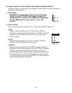
1. Power Switch
WARNING! The power switch does not turn off all power
supply to the unit. 115VACpower supply is present on
control board K1 connector pin #2 (BR) and control board
X1relay (BR) when the power switch is in the "OFF"
position.
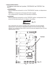
2. Control Switch
The control switch has 3 positions, "ICE," "OFF," and "DRAIN." See Fig. 11.
a) ICE
When the control switch is in the "ICE" position, 24VAC is
directed to control board K8 connector pin #1. 24VAC is present
between control board K8 connector pins #1 (power) and
pin #2 (neutral).
b) OFF
When the control switch is in the "OFF" position, 24VAC is
broken to control board K8 connector pin #1.
c) DRAIN
When the control switch is in the "DRAIN" position, 24VAC is
directed to control board K8 connector pin #1. 24VAC is present
between control board K8 connector pins #1 (power) and
pin #2 (neutral). Also, a 5VDC circuit is closed on control board
K9 connector pins #1 and #2. This energizes an internal relay
on the control board which allows 24VAC to the drain valve from
control board connector K2 pin#10.
CONTROL
DISPENSE MODE
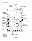
4A1038-014
ICE
OFF
DRAIN
PORTION
CONTINUOUS
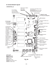
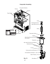
Fig. 10
Fig. 11