


9 569000246
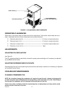
6. Make sure the main power switch (115 VAC, 60 Hz Unit), located on back side of the Unit, is in the “OFF”
(down) position.
7. Plug Unit power cord into electrical outlet. If Unit is 115 VAC, 60 Hz, place main power switch on back side
of the Unit in “ON” position.
8. The compressor, condenser fan motor, and the agitator motor will start and begin forming an ice bank.
When a full ice bank has been formed, the compressor and condenser fan motor will stop but the agitator
motor will continue to operate circulating ice water bath in the water tank. Water will continue to drip from
the water tank overflow tube until a full ice bank has been formed, then the tube may be stored inside the
Unit.
CONNECTING CO
2
SYSTEM TO BEER KEG TAPPERS
(see Figure 2)
WARNING: CO
2
displaces oxygen. Strict attention must be observed in the prevention of
CO
2
(carbon dioxide) gas leaks in the entire CO
2
and soft drink system. If a CO
2
gas leak is
suspected, particularly in a small area, immediately ventilate the contaminated area before
attempting to repair the leak. Personnel exposed to high concentration of CO
2
gas will experience
tremors which are followed rapidly by loss of consciousness and suffocation.
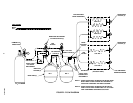
Connect CO
2
system to beer keg tappers as shown in Figure 2. DO NOT INSTALL BEER KEG
TAPPERS IN BEER KEGS AT THIS TIME.
CONNECTING BEER SOURCE SUPPLIES TO UNIT
(see Figure 2)
NOTE: The numbered Unit beer inlet lines are labeled to identify the beer faucets they serve. For exam-
ple: The line labeled No. “1” is connected to system that provides beer to be dispensed from the No. 1
beer faucet (No. 1 beer faucet is faucet on right side when facing front of the Unit).
1. All Unit beer inlet lines internal connections have been made at the factory. Connect Unit beer inlet lines to
beer keg tappers as shown in Figure 2. DO NOT INSTALL BEER KEG TAPPERS IN BEER KEGS AT
THIS TIME.
NOTE: A short length of tubing, with a syrup tank liquid quick disconnect on it’s end (tubing, liquid
quick disconnects, and tee fittings not provided), must be installed in the beer lines close to the beer
keg tappers as shown in Figure 2). Purpose of the liquid quick disconnects is to enable a syrup tank
containing sanitizing solution to be connected into the beer systems.
A length of tubing, with a syrup tank CO
2
quick disconnect on it’s end (parts not provided), must be
installed in one of the beer kegs tappers CO
2
source line as shown in Figure 2). Purpose of the CO
2
quick disconnect is to connect regulated CO
2
gas pressure to the syrup tank containing sanitizing
solution.
2. The beer systems should be sanitized at this time as instructed in SERVICE AND MAINTENANCE section
of this manual.
PREPARING UNIT FOR OPERATION
(see Figure 2)
1. Make sure primary and secondary CO
2
regulators assemblies adjustment screws are backed out until all
tension is relieved from the adjusting screws springs.
2. Make sure shutoff valves, located in CO
2
lines connected between the secondary CO
2
regulators and the
beer kegs tappers, are in the closed positions.