


569000246 12
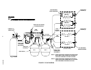
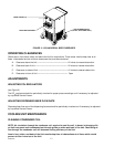
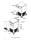
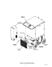
BEER FAUCET (2)
UNIT POWER SWITCH
(115 VAC, 60 HZ UNIT ONLY)
DRIP TRAY/CUP REST
FIGURE 3. 1550 UNIVERSAL BEER DISPENSER
OPERATING CLEARANCES
Check area in front, back, sides, and above the Unit for obstructions. These areas must be kept clear at all
times. Listed below are the minimum clearances that must be maintained.
A. Clearance above the Unit ––––––––––––––––––––––––––––– 12 inches to nearest obstruction.
B. Clearance back of Unit ––––––––––––––––––––––––––––––– 12 inches to nearest obstruction.
C. Clearance on sides of Unit –––––––––––––––––––––––––––––12 inches to nearest obstruction.
D. Clearance on front of Unit ––––––––––––––––––––––––––––– Open
ADJUSTMENTS
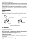
ADJUSTING CO
2
REGULATORS
(see Figure 2)
The CO
2
regulators should be periodically checked for proper pressure settings and if necessary, be adjusted
by a qualified Service Person.
ADJUSTING DISPENSED BEER FLOW RATE
Dispensed beer flow rate of the dispensing faucets should be periodically checked and if necessary, be adjusted
by a qualified Service Person.
COOLING UNIT MAINTENANCE
CLEANING CONDENSER COIL
NOTE: Air circulation through the condenser coil, required to cool the coil, is drawn in through grille
on Unit front panel and is exhausted out through grilles on sides and back of the Unit. Restricting air
flow through the condenser coil will decrease cooling efficiency of the Unit.
Area in front, sides, and back of the Unit must be kept free of obstructions at all times which would
prevent air flow in and out of the Unit.