


4569000246
Table 1. Design Data (cont’d)
Electrical Requirements:
Operating Voltage See Unit Nameplate
Current Draw See Unit Nameplate
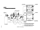
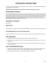
THEORY OF OPERATION
(see Figure 2)
A CO
2
cylinder delivers carbon dioxide (CO
2
) gas through adjustable CO
2
regulators to the beer kegs. When
dispensing valves are opened, CO
2
gas pressure exerted upon the beer kegs pushes beer from the kegs,
through the Unit cooling coils, and on to the beer faucets resulting in cold beer being dispensed.
When the Unit power cord has been plugged into an electrical outlet and the main power switch on back of the
Unit (115 VAC, 60 Hz Units only) has been positioned in the ‘‘ON’’ (up) position, the compressor, condenser fan
motor, and agitator motor will start and begin forming an ice bank. When a full ice bank has been formed, the
compressor and condenser fan motor will stop but the agitator motor will continue to operate, circulating ice wa-
ter bath in the water tank. The water tank ice bank sensing bulb will cycle the compressor and condenser fan
motor on and off as required to maintain a full ice bank.
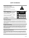
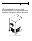
FIGURE 1. 1550 UNIVERSAL BEER DISPENSER