


11 189159000
SERVICE AND MAINTENANCE
This section describes service and maintenance pro-
cedures to be performed on the unit.
IMPORTANT: Only qualified personnel should
service internal components or electrical wiring.
PREPARING UNIT FOR SHIPPING,
RELOCATING, OR STORING
CAUTION: Before shipping, storing,
or relocating this Unit, the syrup
systems must be sanitized and all
sanitizing solution must be purged from the
syrup systems. All water must also be
purged from the plain and carbonated water
systems. A freezing ambient environment
will cause residual water in the Unit to freeze
resulting in damage to internal components.
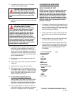
TOP COVER, ACCESS GRILLES, AND
DRIP TRAY REMOVAL (see Figure 3)
TOP COVER REMOVAL
Remove four screws securing unit top cover, then lift
cover straight up and off.
ACCESS GRILLES REMOVAL
Remove four screws securing access grille on unit,
then remove grille.
DRIP TRAY REMOVAL
1. If drip tray drain hose is used, disconnect drain
hose from bottom of drip tray.
2. Lift drip tray up slightly, and at same time, tip
front of drip tray up to disengage its bottom sup-
ports from square holes in unit front panel. Slide
drip tray down to disengage its upper rear edge
from under valve trim panel lip.
3. Install drip tray on unit by reversing removal pro-
cedure.
PERIODIC INSPECTION
4. Check unit condenser coil for accumulation of
dust, lint, and grease which will restrict air flow
through condenser coil which will decrease unit
cooling efficiency.
5. Check area in front, sides, and back of unit for
obstructions. These areas must be kept clear at
all times which would prevent air flow in and out
of unit.
6. Check dispensing valves for dripping that indi-
cates leaking and repair as necessary.
ADJUSTMENTS
ADJUSTING PRODUCT TANKS CO
2
REGULATORS
NOTE: To readjust CO
2
regulator to a lower set-
ting, loosen adjusting screw lock nut, then turn
screw to the left (counterclockwise) until pres-
sure gage reads 5--psi lower than new setting
will be. Turn adjusting screw to the right (clock-
wise) until gage registers new setting, then tight-
en lock nut.
Set product tanks CO
2
regulators, using Cornelius
PRE--MIX COMPUTER slide rule or bottling room
chart, at equilibrium pressure for highest temperature
encountered between product tank storage area and
cooling unit plus 5--psig operating pressure for lines
10--feet in length or less and no vertical lift. Add one
pound for every 10--feet over initial 10--feet of prod-
uct tank--to--cooling unit line length and one pound
for every 2--feet of vertical lift. Add one pound for
every product tank on line over three tanks. MAXI-
MUM UNIT INLET PRESSURE MUST NOT EX-
CEED 100--PSIG. Loosen lock nut on CO
2
cylinder
adjusting screw, then turn adjusting screw to the right
(clockwise) until gage registers desired pressure.
Tighten adjusting screw lock nut.
ADJUSTING DISPENSED PRODUCT FLOW
RATE
Rotate dispensing valve Compensator Adjusting
Screw (Figure 3) to the left (counterclockwise) for
higher product flow rate or to the right (clockwise) for
lower product flow rate.
REPLENISHING CO
2
SUPPLY
NOTE: When indicator on CO
2
cylinder regulator
assembly 2000--psi gage is in shaded (‘ ‘change
CO
2
cylinder’’) portion of dial, CO
2
cylinder is
almost empty and should be changed.
1. Fully close (clockwise) CO
2
cylinder valve.
2. Slowly loosen CO
2
regulator assembly coupling
nut allowing CO
2
pressure to escape, then re-
move regulator assembly from empty CO
2
cylin-
der.
3. Unfasten safety chain and remove empty CO
2
cylinder.