


15 189159000
6. If ice bank is dirty, allow it to melt. Hot water
may be used to speed melting.
CAUTION: Never use an ice pick or
other instrument to remove ice from
evaporator. Such practice can result
in punctured refrigerant circuit or damage to
corrosion protective coating on evaporator
tank.
7. Wash inside of evaporator tank with a mild soap
solution.
CAUTION: Function of the anode in
the ice water bath is to draw
corrosive agents to itself and away
from evaporator tank. Make sure ice bank
sensing bulb and anode, with its rubber
insulator in place on top end, are properly
placed in their respective position. Anode
must be completely insulated from other
metal components and only an aluminum
screw must be used to secure its connecting
wire to evaporator tank. If anode is allowed
to contact other metal parts, its effectivity
will be destroyed, allowing corrosive action
to take place on evaporator tank.
8. Use fiber brush and carefully clean mineral de-
posit build--up from agitator motor shaft, ice
bank sensing bulb, and anode. If after cleaning
anode, and it is found to be badly corroded, re-
place with a new one. Make sure only an alumi-
num screw is used to secure anode connecting
wire to evaporator tank.
9. Rinse all parts and flush evaporator tank with
clean water.
10. Install plug in drain hose, then place hose back
inside unit.
11. Install grille and secure with four screws.
12. Fill evaporator tank (if no ice bank is present)
with approximately 10 gallons of water up to top
of stainless steel product coils. USE LOW--MIN-
ERAL--CONTENT WATER WHERE A LOCAL
WATER PROBLEM EXISTS.
13. Unit with sealed evaporator tank only.
Refer to step 8 CHECKING ICE WATER BATH
and perform procedures to install evaporator
tank cover, connect product tanks into systems,
bleed air from systems, and check for leaks.
14. Flip unit power switch on back of unit to ‘‘ON’’
(up) position. Make sure compressor condenser
fan motor, and agitator motor are operating.
CLEANING AND SANITIZING
DAILY CLEANING OF UNIT
NOTE: Drip tray that is connected to drain hose
routed to waste container or permanent drain
need not be removed from unit to be cleaned.
Remove cup rest, then wash out and rinse drip
tray in place on unit allowing water to escape
through drain hose to waste container or drain.
Wash and rinse cup rest, then install cup rest in
drip tray. If drip tray is not connected to drain,
proceed as follows:
1. Lift drip tray up slightly and at the same time, tip
front of drip tray up to disengage its bottom sup-
ports from square holes in unit front panel. Slide
drip tray down to disengage its upper rear edge
from under valve trim panel lip.
2. Remove cup rest from drip tray. Wash cup rest
and drip tray, then rinse them with potable wa-
ter.
3. Install cup rest in drip tray, then install drip tray
on unit by reversing removal procedure.
4. Rinse out sponge with clean water, then wring
excess water out of sponge. Wipe off external
surfaces of unit, then wipe unit dry with a clean
soft cloth. DO NOT USE ABRASIVE TYPE
CLEANERS.
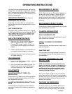
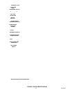
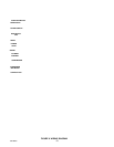
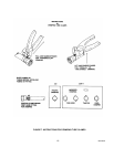
KNOB LEVER BONNET
FRICTION WASHER
COMPENSATOR
O-RING
SHAFT AND
SEAT ASS’Y
BODY
INNER SLEEVE
OUTER SLEEVE
PHILLIPS-HEAD SCREW
SPRING
COMPENSATOR
ADJUSTING
SCREW
LEVER
BALL WASHER
KNOB
O-RING
FIGURE 5. CLEANING DISPENSING VALVE