


12189159000
WARNING: To avoid personal injury
and/or property damage, always
secure CO
2
cylinder with safety chain
to prevent it from falling. Should valve
become accidentally damaged or broken off,
CO
2
cylinder can become an unguided
missile.
4. Position CO
2
cylinder and secure with safety
chain.
5. Make sure gasket is in place inside CO
2
regula-
tor coupling nut, then install regulator on CO
2
cylinder.
6. Open (counterclockwise) CO
2
cylinder valve
slightly to allow lines to slowly fill with gas, then
open valve fully to back--seat valve. (Back--seat-
ing valve prevents leakage around valve shaft).
7. Check CO
2
connections for leaks. Tighten loose
connections.
REPLENISHING PRODUCT SUPPLY
1. Remove inlet (CO
2
) disconnect (grey) and outlet
disconnect (black) from empty product tank,
then remove tank.
2. Place full product tank in position, then connect
inlet (CO
2
) disconnect (grey) and outlet discon-
nect (black) to tank.
PRODUCT FLAVOR CHANGE
Sanitize applicable system as instructed, then install
full tank of new flavor product.
CLEANING CONDENSER COIL
NOTE: Air circulation through condenser coil,
required to cool coil, is drawn in through grille
on front panel and is exhausted out through
grilles on sides and back of unit. Restricting air
circulation through unit will decrease its cooling
efficiency.
Excessive accumulation of dust, lint, and grease on
condenser coil will restrict air flow through coil and
cause a loss of cooling efficiency. Perform following
procedure to clean condenser coil.
1. Flip unit power switch, located on back of unit,
to ‘‘OFF’’ (down) position.
2. Remove four screws securing grille on front
panel, then remove grille.
3. Vacuum or use a soft brush to clean condenser
coil. If available, use low--pressure compressed
air.
4. Install grille on front panel and secure with four
screws.
5. Flip unit power switch to ‘‘ON’’ (up) position.
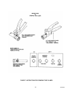
CHECKING ICE WATER BATH (see Figures 3
and 4)
A ‘‘gurgle’’ heard from unit indicates water level in
evaporator tank is low and more water should be
added for maximum product cooling. Before adding
more water, ice water bath and ice bank should be
checked for cleanliness and agitator motor shaft, ice
bank sensing bulb, and anode checked for excessive
mineral deposit build--up.
1. Flip unit power switch, located on back of unit,
to ‘‘OFF’’ (down) position.
2. Remove four screws securing unit top cover,
then lift cover straight up and off.
3. Unit with sealed evaporator tank only.
A. Remove quick disconnects (black) from
product tanks outlets.
B. Relieve pressure from systems by opening
each dispensing valve.
C. Disconnect agitator motor ground wire and
power cord.
D. Disconnect product inlet lines swivel nut
connections from fittings on evaporator
tank cover. Be careful not to lose tapered
gaskets.
E. Remove hex nuts securing evaporator tank
coils line fittings to evaporator tank cover.
F. Remove screws securing evaporator tank
cover to unit, then lift cover straight up to
remove. Be careful not to lose rubber
washers on tank coils line fittings.
4. Check condition of ice water bath and ice bank.
Ice water bath should be clear and ice bank free
of foreign particles.
5. Check agitator motor shaft, ice bank sensing
bulb, and anode for excessive mineral deposit
build--up.
6. If cleaning of evaporator tank is necessary, refer
to CLEANING EVAPORATOR TANK in this sec-
tion.