


InelliCarb Training Manual
© 2004, IMI Cornelius Inc. - 3 - Publication Number: TP01071
INSTALLATION
1. Locate the dispenser indoors on a level counter top.
A. LEG OPTION
Unpack the four (4) legs and install them into the threaded holes provided in the bottom of the
unit. The installer must provide flexibility in the product and utility supply to permit shifting the
position of the dispenser sufficiently to clean the area beneath it.
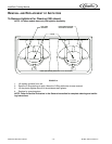
B. COUNTER MOUNTING
If counter mounted the ice drink dispenser must be sealed to the counter. The template drawing
indicates where openings can be cut in the counter. Locate the desired position for the dispenser,
then mark the outline dimensions on the counter using the template drawings. Cut openings in
counter.
Apply a continuous bead of NSF International (NSF) silastic sealant (Dow 732 or equal) approxi-
mately 1/4--inch inside of the unit outline dimensions and around all openings. Then, position the
unit on the counter within the outline dimensions. All excess sealant must be wiped away immedi-
ately.
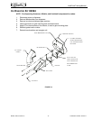
2. The beverage tubes, drain tube and power cord are routed through the large opening in the bottom
of the unit. See the mounting template for locating the required clearance opening in the counter for
these utility lines.
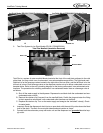
3. Drip tray assembly: Route the drain tube to an open drain with the end of the tube above the “flood”
level of the drain. Use the tubing, fittings, clamps, and insulation provided with the Dispenser to
assemble the drain. The completed drain line must pitch continuously downward and contain no
“traps” or improper drainage will result. Must have a 4 inch air gap between drain line and drain.
NOTE: This equipment must be installed with adequate backflow protection to comply with fed-
eral, state, and local codes.
NOTE: IMI Cornelius Inc. recommends that a water shutoff valve and water filter be installed in
the plain water inlet supply line. A Cornelius Water Filter (P/N 313860000) and QUICK DISCON-
NECT SET (P/N 313867000) are recommended.
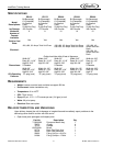
CAUTION: Check the minimum flow rate and the maximum pressure of the plain water inlet supply line.
MINUMUM FLOW RATE MUST BE AT LEAST 125--GALLONS PER HOUR. If flow rate is less than 125-
-gallons per hour, starving of the carbonator water pump will occur. Starving will damage the water pump
and could cause the carbonator to time out. INCOMING PLAIN WATER INLET SUPPLY LINE WATER
TO PUMP PRESSURE MUST REMAIN A MINIMUM OF 10--PSI BELOW THE CARBONATOR C
O2
OPERATING PRESSURE. (Example: Carbonator CO2 operating pressure is 75--PSI and the maximum
water pressure can be no more than 65--psi, etc.). Water over pressure (higher than C
O2 operating pres-
sure) can cause carbonator flooding, malfunction, and leakage through the carbonator relief valve. If
water is exceeding maximum pressure specifications, a Water Pressure Regulator Kit (P/N 310150000)
or equivalent must be installed in the plain water inlet supply line. If fitting connector is not available,
water line must be 1/2” or 3/4” diameter with a shut off valve within 6 feet of the dispenser.
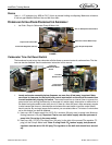
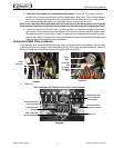
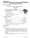
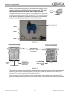
4. Locate the carbonator pump assembly and connect probe wires from Ice/Drink Unit and pump. Con-
nect inlet water to pump and pump outlet to Ice/Drink Unit using 3/8--inch food--grade tubing.
NOTE: Locate carbonator assembly within 6 feet of the dispenser. Do not lengthen the control
board harness.
5. Connect the beverage system product tubes as indicated in applicable Plumbing Flow Diagram, see
page 19. This work should be done by a qualified service person.
NOTE: Water pressure for non carbonated beverages must be 60 P.S.I. minimum.
NOTE: See applicable Flow Diagram or Decal on the lower front of the unit for the location of
syrup and water connections.
6. Clean the hopper interior.
7. Connect the two power cords to a 120 volt, 60 cycle, 3-wire grounded receptacle. For 220--240 Volt
International Units, a 3--wire power cord is provided. An adapter plug for the particular country will
need to be provided by the Installer.