


InelliCarb Training Manual
© 2004, IMI Cornelius Inc. - 5 - Publication Number: TP01071
C. Initial start-up procedure for carbonated water system: Turn on the CO
2
supply to the car-
bonator tank, vent air from carbonator tank by pulling the tank relief valve. Turn on water supply to
the pump. Connect electrical power to the pump and motor unit. Bleed the air out of the system
by energizing a beverage valve until carbonated water is flowing from the valve.
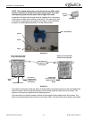
NOTE:If the carbonator Pump and Motor does not cycle (turn on and off) properly, check that the
probe harness connector and ground lead are secured to the carbonator tank connection points.
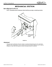
D. If service is required on Ice Drink units, it will be necessary to lower the beverage valve panel to
gain access to the probe and ground connection. Remove the lower front panel (2 screws) from
the cabinet and the ice chute cover (“snap” fit). Remove the 6 screws that secure the beverage
panel to the cabinet. The panel can now be moved downward due to the flexibility of the beverage
tubing to expose the carbonator tank connections.
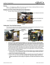
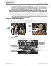
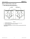
Carbonator Relief Valve Locations
The carbonator tank is located behind the splash panel, on the right side of the dispenser. You will need
to pull the relief valves to purge air from the system after the CO
2
supply has been hooked up. Failure to
do this will cause low carbonation volume and popping of the relief valves.
FIGURE 6
FIGURE 7
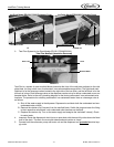
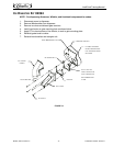
2. Dispenser
Ice Drink Model ED175BCH (Lower Front Panel Removed)
FIGURE 8
Relief
Valve Ring
Agitator
Motor
Carbonator
Tank
Carbonator
Tank Relief
Valve
Cold Plate Inlets
(3/8 Barb)
Carb. Tank Liquid
Level Probe Harness
Total Flex Manifold
(with insulation)
Carb Tank CO
2
Supply Line
Total Flex Manifold
(insulation removed)
Insulated Cold Plate
Cover & Carbonator
Tank Assembly