


9 91704
OPERATING INSTRUCTIONS
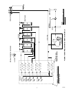
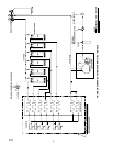
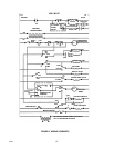
A tem perature sensing control bulb located in the storage hopper starts and stops the ice-making process in
response to ice level in the hopper. Wit h this ice level control “calling”for ice (hopper ice level is low), ice begins
to f orm on the stainless steel t ubing coils in t he evaporator section of the ice-maker. Ice continues to “grow” on
the evaporator coil until it contacts the ice thickness probe (low voltage conductivity sensor). At this point, the
conductivity probe triggers the harvest tim er motor. The harvest timer contains five (5) cam operated switches
which function as detailed in the following table.
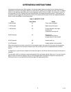
Table 3. HARVEST CYCLE
Tim e Ca m Switch Action
0--86 Seconds #1 Timer m otor energized.
1--23 Seconds #4 Water dump valve open.
1--36 Seconds #2 Hot gas solenoid valve open.
Air pump off.
Condenser fan motor off.
36--90 Seconds #2 Air pump on.
Condenser fan motor on.
Hot gas solenoid valve closed.
35--60 Seconds #3 Harvest mot or on.
44--48 Seconds #5 Hopper agitator motor operates.
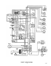
When ice contacts the ice lever control bulb in the storage hopper, the control will shut down the refrigeration
syste m. If this signal occurs during the harvest cycle, the harvest cycle wil l be completed before shutdown
occurs.
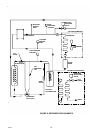
To dispense ice, push the lever located on the lower front panel. Ice will flow from the ice chute until t he lever is
released.
For units with a built-in cold plate, ice will automatically fill the cold plate cabinet. Allow one (1) hour for the cold
plate t o reach it s maximum capacity. Start up the beverage system and adjust the faucets to the proper brix.
Pushing the lever on any faucet will provide beverage of the appropriate flavor.