


291704
INSTALLATION INSTRUCTIONS
UNPACKING INSTRUCTIONS
1. With the unit upright, carefully remove the shipping crate. Inspect for shipping damage and report any such
damage t o the shipper immediately.
2. Unlock and open the hinged service door on the upper left side panel.
3. Remove shipping tape from the ice drop cover, storage hopper cover, water float valve and agitator in the
storage hopper.
4. Remove shipping tape from air inlet filter and sink grill.
INSTALLATION INS TRUCTIONS
NOTE: A Cornelius Model XXXX water filter(or equal) ice maker quality water treatment unit MUST BE
INSTALLED in the water supply line to the ice maker. Failure to do so may result in poor
quality ice, low production output, and may cause premature failure of the i ce maker
evaporator and void the extended evaporator warranty.
This ice maker is provided with a stain less steel
evaporator designed to last the life of the
product. But, some of the chemicals in treated and untreated water, specifically chlorine and
sulphur (sulphide), have the ability to attack stainless steel and cause premature failure. An
initial investment in proper water treatment wil l pay for itself in increased production, quality
and long life of the product.
1.
Location
Locate the ice m aker/dispenser indoors in a well-ventilated area. Avoid exposure to direct sunlight and/or
heat caused by radiation.
Ambient room temperature must be in the range of 60° to 90° F. Do not install unit in an enclosed area
where heat build up could be a problem . For proper airflow for the refrigeration system, allow a 6
clear-
ance at the back of t he unit
anda12 clearance at the right side panel.
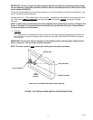
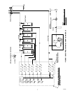
Consult Figure 1 f or utility connection location.
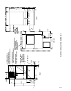
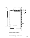
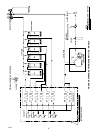
Consult Figure 2 f or dimensions for mounting the unit t o the counter with the hardware provided. Note that
the uni t must be level for proper operation.
The unit must be sealed
to t he counter. The mounting template drawing (Figure 2) indicated t he openings
which must be cut in the counter. Locate t he desired position for t he unit, then mark t he outline dimensions
and cut-out locations using the t emplate drawing. Cut openings in counter.
Apply a continuous bead of NSF International (NSF) listed silastic sealant (Dow 732 or equal) approximate-
ly 1/4
inside of the unit outline dimensions and around all openings. Then position t he unit on the counter
within the outline dimensions. All excess sealant must be wiped away.
2.
Plumbing
Connect the ice maker to a cold, potable water source suitable for drinking. Do not install the unit on a
water soft ener line. It is recommended that a hand shut-off valve and strainer be used on the incoming
supply line. A 1/4
outside diameter compression tube fitt ing is provided at the back of the unit for t he wa-
ter supply hook up (See Figure 1). For p roper operation, the incoming water supply pressure must be in the
range of 30--90 PSI G. Install a pressure regulat ing valve if above this range.