


11
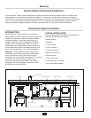
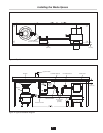
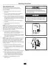
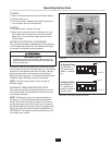
WASTE INLET LINE
Connect the disposer outlet flange as close as
possible and with as few as possible 90° elbows to
the Waste Xpress inlet.
NOTE: The maximum allowable distance between the
disposer outlet flange and the Waste Xpress inlet is
10 feet with a maximum of four (4) 90° elbows.
1. Connect the disposer outlet to the Waste Xpress
inlet using 2" NPT plumbing. 3 HP will require 3"
outlet adapter. The run between the disposer and
Waste Xpress should have 1/4" slope per foot and
must comply with all local codes.
NOTE: All horizontal runs should be as short as
possible (not to exceed 10 ft.), with an approximate
fall of 1/4" per foot.
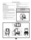
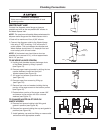
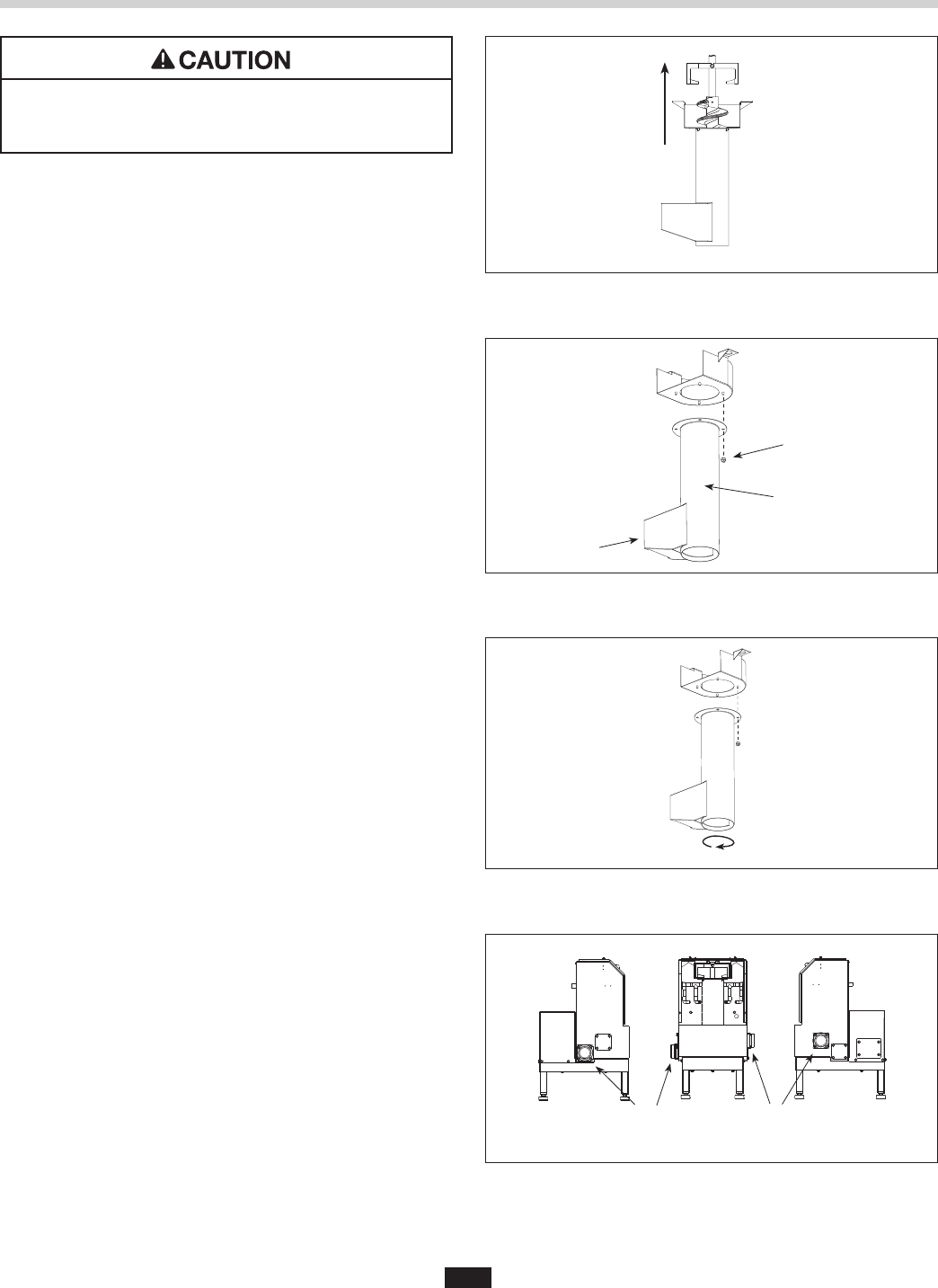
TO REVERSE AUGER SCREEN:
A. Holding both handles remove discharge chute
of the Waste Xpress by tilting it upward
(see Figure 13).
B. Remove auger-bearing bracket by sliding the two
captive fasteners inward and then pull
bracket upward (see Figure 14).
C. Lift auger and screen up and then out
(see Figure 14).
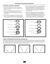
D. Remove auger from screen by lifting up
(see Figure 15).
E. Remove four nuts and washers holding the top
portion of the auger screen to the bottom portion
(see Figure 16).
F. Rotate bottom portion of the auger screen 180°
and secure to top portion with four nuts and
washers (see Figure 17).
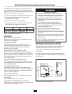
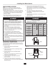
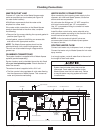
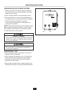
TO CHANGE WASTE INLET SIDE ON
WASTE XPRESS:
A. Remove four screws holding inlet fitting and
gasket in position (see Figure 18).
B. Remove four screws holding the cap and gasket in
position (see Figure 18).
C. Install gaskets, cap and inlet fitting on reverse side
and secure with appropriate screws.
Figure 15.
Figure 16.
Figure 17.
Plumbing Connections
Nuts &
Washer (4)
Auger
Screen
Inlet
Figure 18.
Waste
Outlet
Waste
Inlet
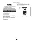
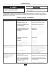
PROPERTY DAMAGE
Water connections must comply with all local
plumbing codes.