


13
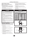
PROPERTY DAMAGE
• Ensure that control center voltage and phase
match the disposer motor and electrical supply.
Check nameplates on disposer and control
center for voltage and phase specifications.
• Refer to the control center wiring diagrams in
this manual for correct connection.
• Use NEMA 4 watertight electrical connectors
(not supplied) when making electrical connections
to the control center.
ELECTRICAL SHOCK
• Turn off all electrical supply to the disposer before
attempting any work on it. Use a voltmeter or
circuit tester to ensure that power is off.
• All Installation work must conform to local
plumbing and electrical codes.
• All components (disposer, WX, control center
and solenoids) must be carefully and permanently
grounded.
• A properly fused disconnect must be installed at
the electrical supply source for the control center.
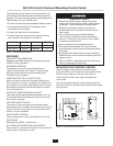
• The control center’s door disconnect must be in the
off position before the panel door can be opened.
Power is still present at the disconnect until power
is turned off at the electrical supply source.
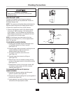
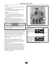
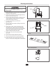
LINE VOLTAGE
Connect the incoming line power to the electrical
disconnect switch and connect the disposer motor to
labeled terminal blocks in the control center. Use the
appropriate voltage and phase wiring diagram(s) in
the Wiring Diagram section at the end of this manual.
A wiring diagram is also located on the inside door of
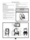
the control center. Wire the disposer motor for correct
voltage using the connection diagram inside the motor
terminal box.
LOW VOLTAGE
The WX-101A control center uses low voltage (24 V)
to operate contactor coils, solid state control circuit,
push buttons, and solenoid valves. Red wires denote
a 24 V circuit.
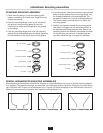
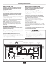
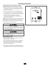
COLD WATER SOLENOID VALVE
One 24 V cold water solenoid valve is supplied with
control centers. Connect solenoid valve to terminals 4
and 13. Supplied flow control valve is to be connected
to cold water line.
Wire per local electrical code using NEMA 4 water-tight
electrical connections.
HOT WATER SOLENOID VALVE
One 24 V hot water solenoid valve is supplied with
control centers. Connect solenoid valve to terminals 7
and 18. No flow control valve is to be used on hot water
line. Use 1/2" compression fitting to connect hot water
line to Waste Xpress.
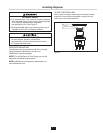
PERSONAL INJURY
Disconnect electricity at line disconnect switch
before servicing system.
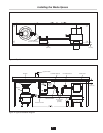
Electrical Connections