


10
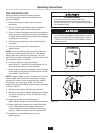
ELECTRICAL SHOCK
• Ensure that Waste Xpress voltage and phase
match that of the electrical supply, control center &
disposer. Check nameplate for specification.
• Electrical connections should be made by a
qualified electrician and should comply with all
local codes.
• Turn off electrical supply to Waste Xpress,
control center & disposer before attempting to
work on it. Test with a volt meter or circuit tester
to ensure that power is off.
• Do not operate unit with panels removed.
• All components (disposer, WX, control center
and solenoids) must be carefully and permanently
grounded.
• A properly fused disconnect must be installed at
Waste Xpress, control center & disposer electrical
supply source.
• Use only NEMA 4 watertight electrical connectors
when connecting to junction box.
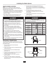
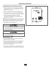
WASTE XPRESS LOCATION
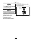
NOTE: Prior to installing the Waste Xpress the
disposer and control center should be installed as
specified within this manual.
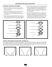
• Position Waste Xpress within 10 feet of the disposer
outlet flange. A maximum of four (4) 90º elbows can
be used between the disposer and Waste Xpress
(prefer 45º elbow).
• Level Waste Xpress by turning the legs in or out
with a wrench. Place a level on top of the unit.
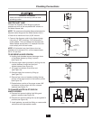
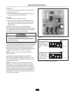
ELECTRICAL CONNECTIONS
The Waste Xpress system requires power only to the
control center. The control center powers the disposer
and Waste Xpress.
1. Remove retaining screw and disposer
electrical cover.
2. Open control center cover by loosening locking
clamps securing it.
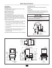
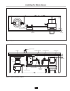
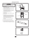
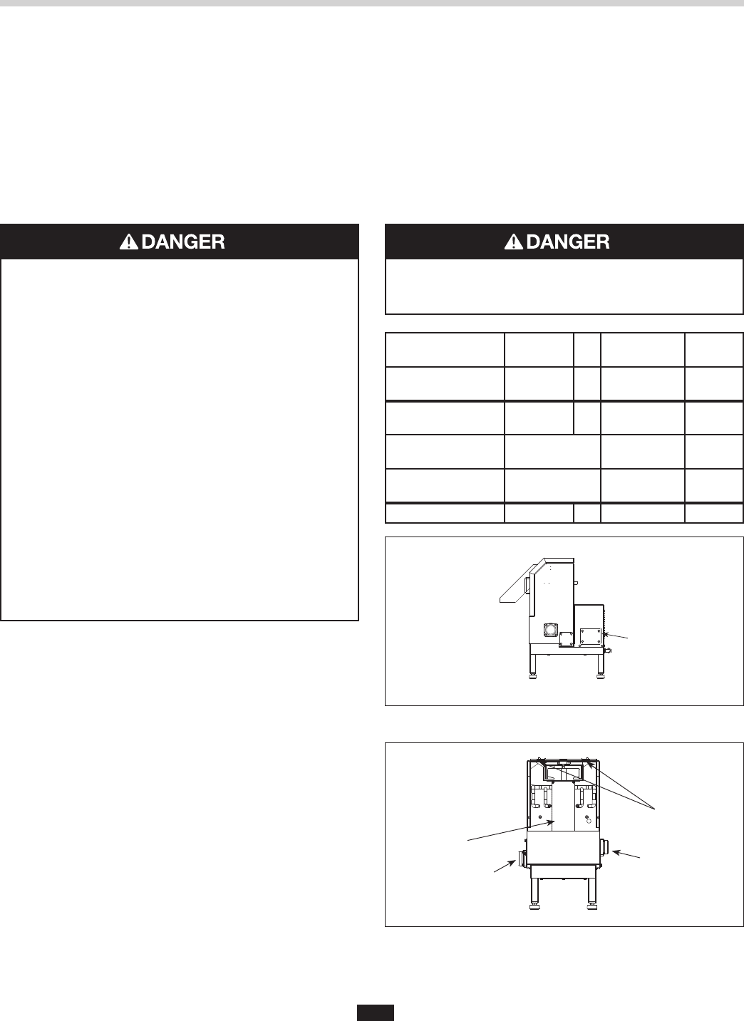
3. Remove terminal cover from Waste Xpress
(see Figure 13).
4. Connect incoming power line to electrical door
disconnect switch in WX-101A.
5. Connect disposer motor leads to terminal
block locations.
6. Connect cold water solenoid to appropriate
terminals 4 and 13. Connect hot water solenoid to
terminal 18 and 7.
7. Connect wire bundle between WX-101A and
Waste Xpress unit as detailed in wiring diagram.
Door interlock connections are #3 and #95. Replace
terminal cover.
8. Wire per local electrical codes and install
using NEMA 4 watertight electrical connectors
(not supplied).
9. Install disposer terminal box cover and secure with
retaining screw.
10. Secure WX-101A cover with locking clamps.
ELECTRICAL SHOCK
Do not pinch or damage the electrical wires when
installing the terminal box.
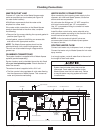
WX
Terminal
WX-101A
Terminal
Voltage
WX Auger Motor
3 Phase
T1, T2, T3 To T1, T2, T3 Line
WX Magnetic
Interlock
3, 95 To 3, 95 24V
Cold Water Solenoid
(Disposer)
4, 13 24V
Hot Water Solenoid
(WX Spray)
7, 18 24V
Disposer To See Diagrams Line
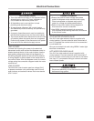
Installing the Waste Xpress
Terminal
Cover
Captive
Fasteners
Waste Inlet
Waste Outlet
Auger
Screen
Figure 13.
Figure 14. Cover Removed