


6
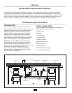
The WX-101A Control Center is UL
®
approved for use
with InSinkErator Waste Xpress food waste reduction
systems. The control center operates the disposer and
Waste Xpress. Its main functions are:
• To start and stop the disposer/Waste Xpress system.
• To reverse the direction of the disposer motor
automatically upon restart.
• To start the water flow to the disposer.
• To allow water flow for several minutes to flush the
drain line after the disposer is turned off.
Model Part No. Voltage Phase
WX-101A-3 14479B 208/230V 3
WX-101A-4 14479C 380/460V 3
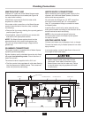
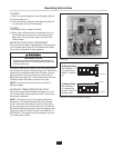
FEATURES
SINGLE BUTTON OPERATION
Disposer and Waste Xpress are controlled by simple
ON/OFF button operation.
AUTOMATIC REVERSE
The disposer motor will reverse its direction of
rotation automatically upon restart. To avoid motor
damage, a delay feature prevents reversing until
the post flush is complete.
WATER SHUTOFF DELAY (POST FLUSH)
After the motor is turned off, the water continues to
flow for up to 10 minutes. The length of this post flush
is controlled by the water shutoff delay timer. The post
flush helps ensure that ground food waste is flushed
out of the drain line.
AUTOMATIC TIMED DISPOSER SHUTOFF
This water saving feature allows the system to run for
10 minutes before it automatically shuts off and must
be manually restarted.
LINE DISCONNECT SWITCH
The switch on the front panel of the control center
disconnects the line voltage. It interlocks with the front
cover so that the cover cannot be opened unless the
switch is in the off position.
LOW VOLTAGE CONTROL
Control operates on a 24 V solid state control circuit.
ENCLOSURE
Stainless steel NEMA 4 construction.
WX TIMER HOT WATER SPRAY ADJUSTABLE
Factory set for 2 minutes off 10 second on controls hot
water spray for cleaning of screen.
Table 1. Electrical Specifications
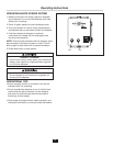
WX-101A Control Features/Mounting Control Center
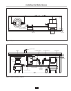
15-1/8"
(384.2 mm)
14"
(355.6 mm)
15-3/4"
(400.1 mm)
9-7/8"
(250.8 mm)
8-1/4"
(209.6 mm)
5-1/4"
(133.4 mm)
5-5/16"
(134.9 mm)
6-3/4"
(171.5 mm)
1"
(25.4 mm)
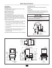
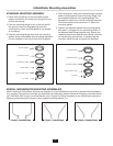
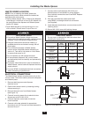
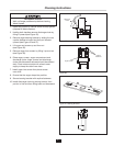
MOUNTING THE CONTROL CENTER
Use the flanges at the back of the control center
enclosure and only mount panel in the upright vertical
position (door hinge is on the left). See Figure 4.
Locate control center within sight of disposer per
local codes.
If box is mounted to the sink table, recess the box so
that the buttons do not extend beyond the table’s edge
(see Figure 4).
Figure 4. Control Center Dimensions
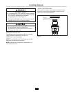
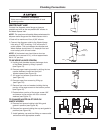
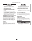
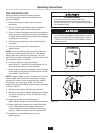
ELECTRICAL SHOCK
• Ensure that Waste Xpress voltage and phase
match that of the electrical supply, control center
& disposer. Check nameplate for specification.
• Electrical connections should be made by a
qualified electrician and should comply with all
local codes.
• Turn off electrical supply to Waste Xpress,
control center & disposer before attempting to
work on it. Test with a volt meter or circuit tester
to ensure that power is off.
• Do not operate unit with panels removed.
• All components (disposer, WX, control center
and solenoids) must be carefully and permanently
grounded.
• A properly fused disconnect must be installed at
Waste Xpress, control center & disposer electrical
supply source.
• Use only NEMA 4 watertight electrical connectors
when connecting to junction box.