


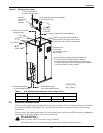
Installation
14
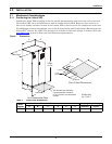
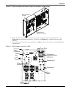
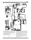
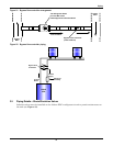
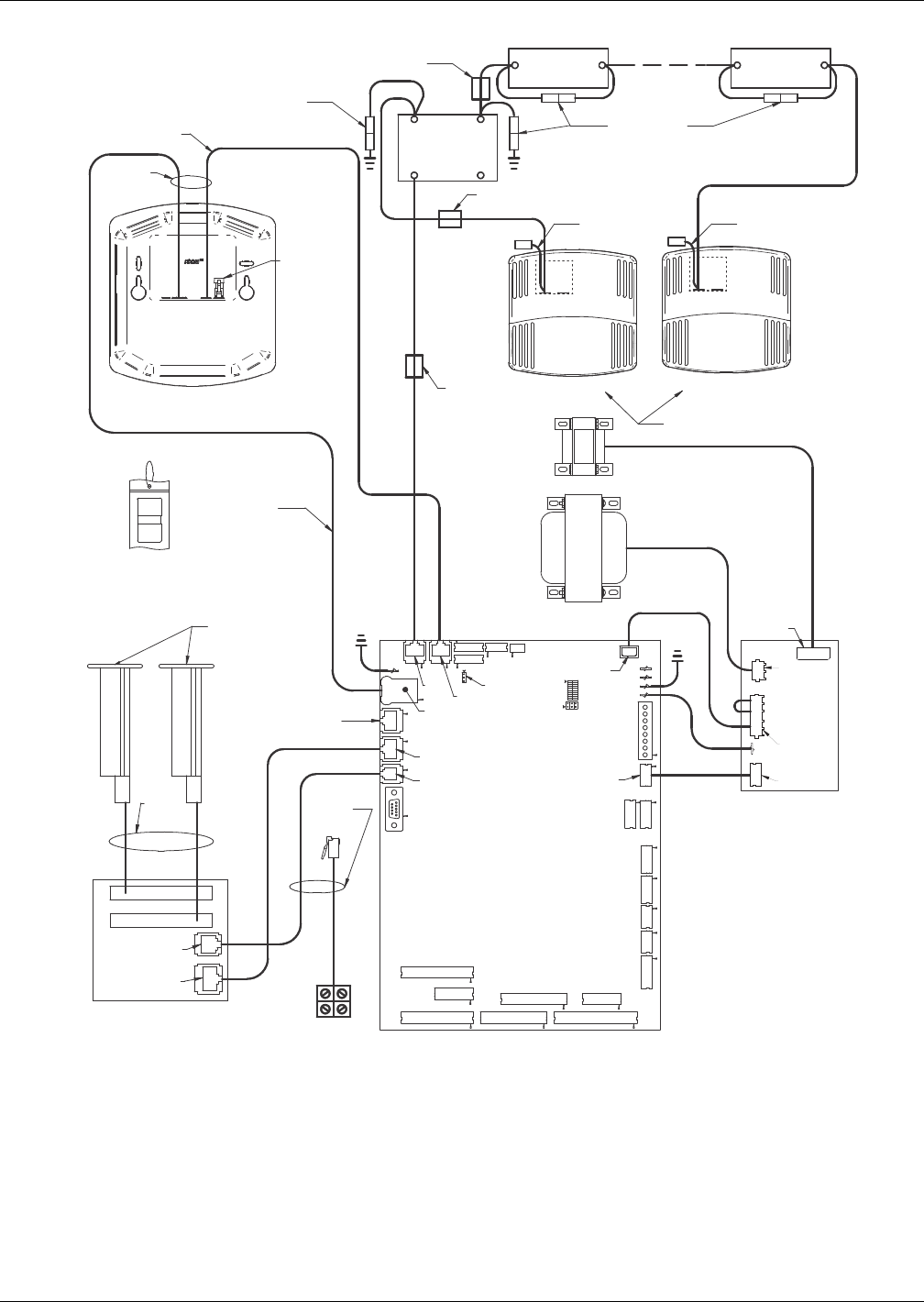
Figure 14 Connecting the remote temperature/humidity sensors
E1
P22 P38 P39 P53 P52
P54
P51
TB1
P63
P18
P11
P12
P13
P7
P32
P8
P40
P33
P34
P36
P35
E5
E1
E2
E3
E4
OFF ON
2
1
4
3
6
5
SW
2
P68
78
P66
P67
P64
P65
P61
P4
P43
P41
P24
P45
P4
P3
P65
P1
P2
P2 P4
P3P1
CAN Iso
Adapter
P66
P67
1
2
3
P78
See
Note 2
See
Note 4
See Note 4
See Note 5
See Note 5
See
Note 9
See Note 7
Remote T/H Sensor BRemote T/H Sensor A
See Note 3
See Note 8
See Note 8
Liebert iCOM Microprocessor
and I/O Board
Not
Used
Cable A
Cable B
Ribbon
Cables
Liebert IntelliSlot
Power Supply
Red Crossover
Ethernet Cable
See Table for
Plug Assignments
CAN
Cable
Termination
Plug
CAN Ground
Coupler
CAN Ground
Coupler
Liebert XD
Cooling Module
P66
P67
P66
P67
P66 P67
Liebert XD
Cooling Module
Crossover Coupler
See Note 6
Unit Display
(Rear View)
Control
Fuse
Board
24VAC Nominal
302211
Rev. 2
T1 Unit Control
Transformer
T6 Isolation
Transformer
Liebert IntelliSlot 1
Liebert IntelliSlot 2
P66P64
P67
77
1. See unit electrical schematic, installation and user manuals.
2. Cables “A” and “B” provided with each unit. Only one is used as follows:
Liebert IntelliSlot-based communications - Cable “A” is preconnected to P65
on microprocessor and input/output board and P65 on Liebert IntelliSlot
power supply non-Liebert IntelliSlot-based communications - Vable “B” is
pre-connected to Terminals 77 and 78 but must be exchanged with Cable “A”
at P65 on the microprocessor and input/output board.
3. Install applicable Liebert IntelliSlot cards.
4. Both cables (P64 and P66) are required.
5. It is not necessary to connect ground coupling on end of cable connected
to Sensor “A” or Sensor “B.”
6. A crossover coupler is provided for unit-to-unit (U2U) networking. Unplug
the red cable from P64 on the microprocessor and input/output board
and connect to one side of the crossover coupler. The first customer
connection point is to P64 on the microprocessor and input/output board.
The second customer connection point is to the other side of the crossover
coupler. This connects the microprocessor and input/output board and
display to the private U2U network.
7. The remote sensors are interchangeable as to which connects to the
Liebert XD cooling module and which connects to P2 on CAN Iso.
8. Field-install cables with factory-installed ferrite beads (when provided,
typical two places). Each cable must make three passes through the ferrite
bead. Locate the ferrite bead on top of the electric box. See instruction
sheet provided with the cable assembly.
9. Factory-installed ferrite bead (when provided). Cable passes through
ferrite bead three times