


Liebert iCOM Control—Firmware Version XP1.00.010.STD
39
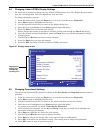
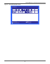
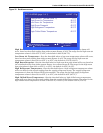
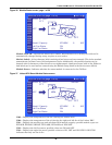
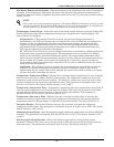
Figure 36 Module Status screen, page 1 of 20
Module Node ID—The location within the CANbus. Each module’s ID is factory-set to 80 and is
automatically changed during setup; requires no user action.
Module Labels—A four-character label consisting of two letters and two numerals. This is the standard
nomenclature for Data Center Grid assignment of racks. Additionally, the module’s location can be
denoted with 10 characters, either letters or non-alphanumeric characters from a built-in list. Either or
both labels can be used and are entered using the Module Setup found in the Service menu (S910).
Module Status—Indicates whether the smart module is connected to the CANbus.
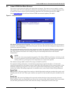
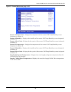
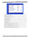
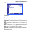
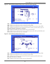
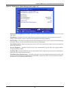
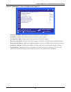
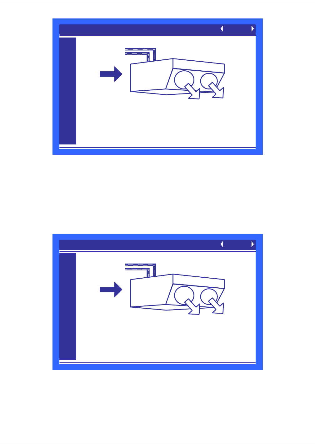
Figure 37 Liebert XDV Smart Module Status screen
U905—Displays the temperature of the air entering the Liebert XDV.
U908—Displays the temperature of the air leaving the right and left fan of the Liebert XDV.
U911—Displays the module type and calculated local module capacity; possible module types are
XDV8SK, XDV8SS, XDV8ST, XDV10SK, XDV10SS and XDV10ST.
U912—Displays the left fan status; possible values are ON and OFF.
U913—Displays the right fan status; possible values are ON, OFF and ON ECON. ON ECON
indicates that only one fan is On.
MODULE STATUS (page 1 of 20) UNIT 01
U901
U902
U903
U904
U905
U906
U907
U908
U909
U910
U911
U912
U913
Model / Capacity XDV8SK 8 KW
Left Fan Status ON
Right Fan Status ON
ONLINE
65°F
NODE 81 AZ81
57°F
92°F
66°F
XDV
MODULE STATUS (page 1 of 20) UNIT 01
U901
U902
U903
U904
U905
U906
U907
U908
U909
U910
U911
U912
U913
Model / Capacity XDV8SK 8 KW
Left Fan Status ON
Right Fan Status ON
ONLINE
65°F
NODE 81 AZ81
57°F
92°F
66°F
XDV