Liebert iCOM Control—Firmware Version XP1.00.010.STD
55
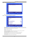
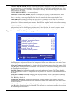
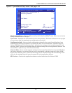
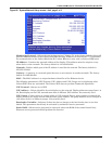
WATER UNDER FLOOR—Enables or disables the Water Under Floor event, which occurs when
the Customer Input 1 is configured for “Water Under Floor” and 24VAC is applied to the input. Sets
how the event is reported: as an alarm, a warning or a message. Specifies how long the control waits
before reporting the event.
UNIT X DISCONNECTED—Not currently used.
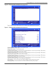
WORKING HOURS EXCEEDED—Enables or disables the Working Hrs Exceeded event, which
occurs when a component has exceeded the user-specified limit. Sets how the event is reported: as an
alarm, a warning or a message. Specifies how long the control waits before reporting the event.
CALL SERVICE—Enables or disables the Call Service event, which occurs when the Customer
Input 1 is configured for “Call Service” and 24VAC is applied to the input. Sets how the event is
reported: as an alarm, a warning or a message. Specifies how long the control waits before reporting
the event.
LOSS OF POWER—Enables or disables the Loss of Power event, which occurs when the unit is On
and operational and the 24VAC power to the control is lost. Sets how the event is reported: as an
alarm, a warning or a message. Specifies how long the control waits before reporting the event.
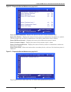
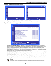
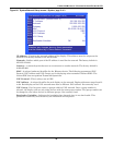
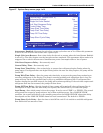
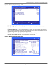
Figure 60 Sensor Calibration/Setup screen, page 1 of 3
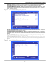
Temperature Sensor A—Adjusts the temperature reading from the actual remote CAN Temp
Humidity sensor designated as Sensor A to compensate for any error of the sensor or to match other
sensors in the room.
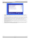
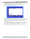
Calibrated Temperature Sensor A—Displays the adjusted temperature value of the remote CAN
Temp Humidity sensor designated as Sensor A. This value is the actual sensor reading plus or minus
the offset Temperature Sensor A.
Humidity Sensor A—Adjusts the humidity reading from the actual remote CAN Temp Humidity
sensor designated as Sensor A to compensate for any error of the sensor or to match other sensors in
the room.
Calibrated Humidity Sensor A—Displays the adjusted humidity value of the remote CAN Temp
Humidity sensor designated as Sensor A. This value is the actual sensor reading plus or minus the
offset Humidity Sensor A.
Temperature Sensor B—Adjusts the temperature reading from the actual remote CAN Temp
Humidity sensor designated as Sensor B to compensate for any error of the sensor or to match other
sensors in the room.
Calibrated Temperature Sensor B—Displays the adjusted temperature value of the remote CAN
Temp Humidity sensor designated as Sensor B. This value is the actual sensor reading plus or minus
the offset Temperature Sensor B.
SENSOR CALIBRATION/SETUP (page 1 of 3) UNIT 01
to confirm
for next/previous unit
then
to select parameter
to change parameter
PASSWORD (Actual Level 0)
Temperature Sensor A
Calibrated Temperature Sensor A
Humidity Sensor A
Calibrated Humidity Sensor A
Temperature Sensor B
Calibrated Temperature Sensor B
Humidity Sensor B
Calibrated Humidity Sensor B
S601
S602
S603
S604
S605
S606
S607
S608
S609
S610
S611
????
+0.0°F
70.3°F
+0.0°F
38.3%
+0.0°F
72.3°F
+0.0°F
35.6%


