


Installation
15
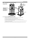
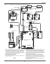
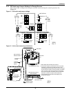
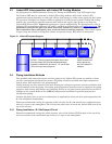
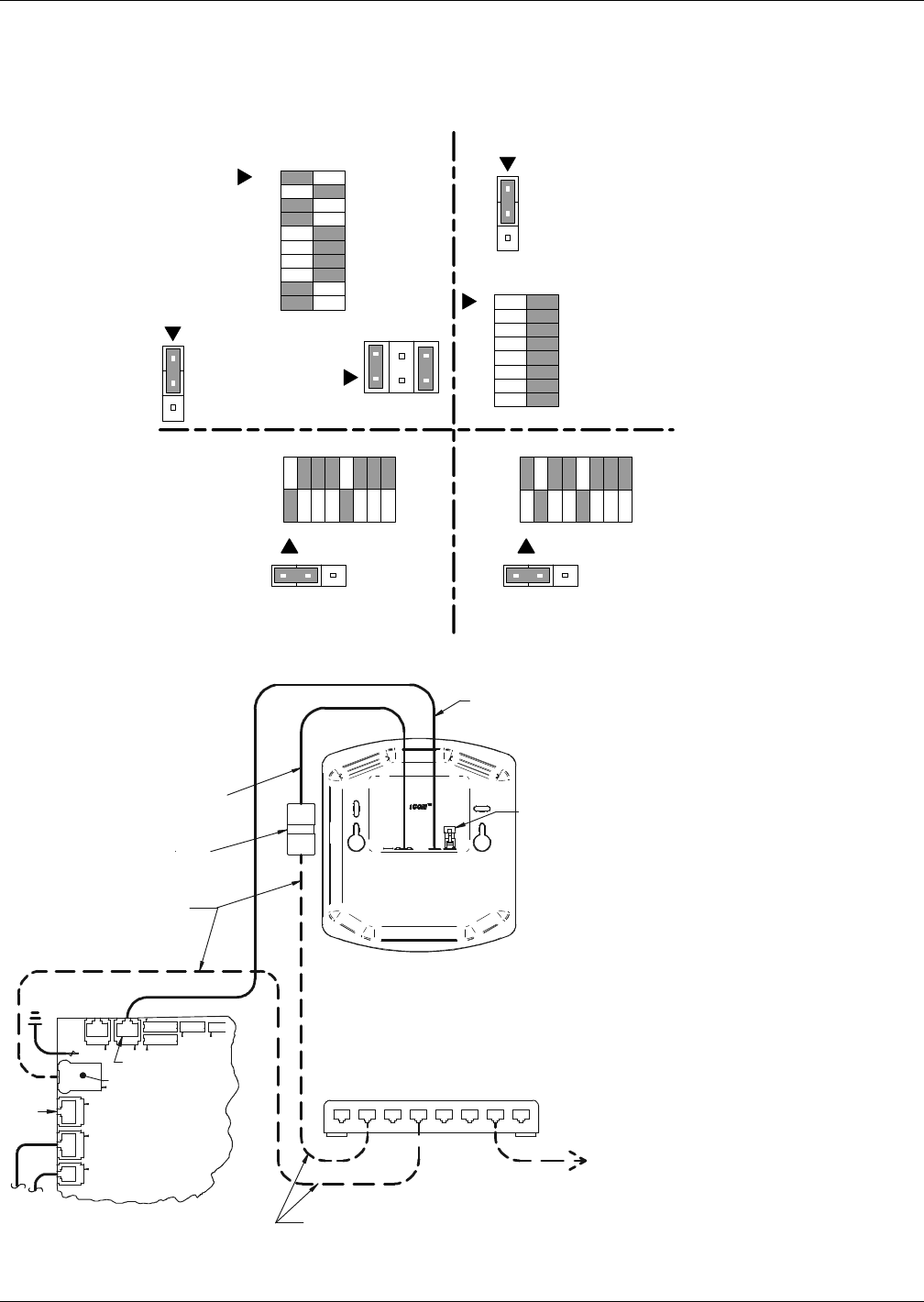
2.2.3 DIP Switch and Jumper Settings for Remote Sensors
The Liebert XDP is shipped with jumpers and DIP switch settings for normal operation. See
Figure 15.
Figure 15 DIP switch and jumper settings
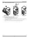
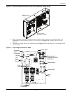
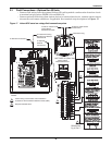
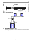
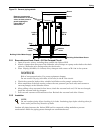
Figure 16 Unit-to-unit networking connections
P68
135
246
SW2
MICROPROCESSOR AND I/O BOARD
REMOTE T/HSENSOR “A” REMOTE T/H SENSOR “B”
SW1SW1
OFF
ON
OFF
ON
Jumper
on 1-2
1
2
3
P78
DIP
Switches
ON
1
3
4
9
10
OFF
2
5
6
7
8
Jumpers
on 1-2, 5-6
OFF ON
1
2
3
4
5
6
7
8
9
10
DIP
Switches
ON
None
OFF
1
2
3
4
5
6
7
8
1
2
3
P78
UNIT DISPLAY
Jumper on 1-2
1 2 3 4 5 6 7 81 2 3 4 5 6 7 8
DIP
Switches
ON
1
5
OFF
2
3
4
6
7
8
DIP
Switches
ON
2
5
OFF
1
3
4
6
7
8
SW3
1
2
3
4
5
6
7
8
OFF ON
P3
321
Jumper
on 2-3
P3
321
Jumper
on 2-3
302211
Rev. 2
302211
Rev. 2
Terminatio n
Plug
Liebert iCOM
Microprocessor
& I/O Board
Customer
Connection
Points
Crossover
Coupler
Red Crossover
Ethernet Cable
Straight Through
Ethernet Cables
U2U Networking Switch
(Field Supplied)
Unit Display (Rear View)
Not
Used
P64
P66
P64
P66P67
To / From Other
Networked Units
CAN Cable
See Note 1
P65
E5
P61
P63
P11 P13
P7
P12
P67
1. Both cables (P64 and P66) are required.
2. A crossover coupler is provided for unit-to-unit (U2U)
networking. Unplug the red cable from P64 on the
microprocessor and I/O board and connect to one side
of the crossover coupler. The first customer connection
point is to P64 on the microprocessor and I/O board.
The second customer connection point is to the other
side of the crossover coupler. This connects the
microprocessor and I/O board and display to the
private U2U network.