Liebert iCOM Control—Firmware Version XP1.00.010.STD
40
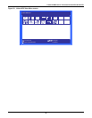
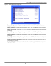
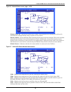
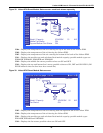
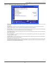
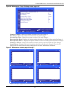
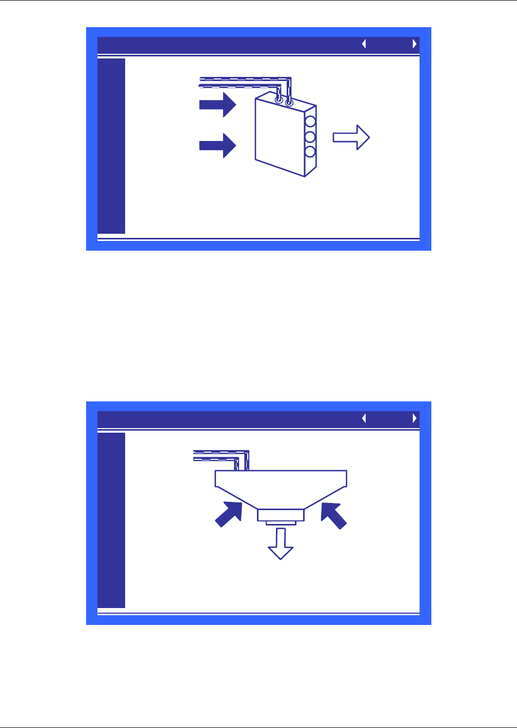
Figure 38 Liebert XDH Smart Module Status screen—each bank shown separately
U904—Displays the temperature of the air entering the top of the bank of the Liebert XDH.
U905—Displays the temperature of the air leaving the Liebert XDH.
U907—Displays the temperature of the air entering the bottom of the bank of the Liebert XDH.
U911—Displays the module type and calculated local module capacity; possible module types are
XDH20SK, XDH20SS, XDH32SK and XDH32SS.
U912—Displays the middle fan status; possible values are ON and OFF.
U913—Displays the top and bottom fans’ status; possible values are ON, OFF and ON ECON. (ON
ECON indicates that two fans have been turned On.)
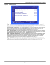
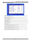
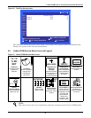
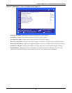
Figure 39 Liebert XDO Smart Module Status screen
U907—Displays the temperature of the air entering from the right and left of the Liebert XDO.
U910—Displays the temperature of the air leaving the Liebert XDO.
U911—Displays the module type and calculated local module capacity; possible module types
XDO16SK, XDO16SS and XDO20SS.
U912—Displays the fan status; possible values are ON and OFF.
MODULE STATUS (page 1 of 20) UNIT 01
U901
U902
U903
U904
U905
U906
U907
U908
U909
U910
U911
U912
U913
NODE 82 AA82
57°F
98°F
98°F
Model / Capacity XDH32SK 15 KW
Middle Fan Status ON
Top and Bottom Fan Status ON
ONLINE
73°F
XDH
TOP/
BOTTOM
XDO
92°F92°F
68°F
MODULE STATUS (page 1 of 20) UNIT 01
U901
U902
U903
U904
U905
U906
U907
U908
U909
U910
U911
U912
U913
Model / Capacity XDO20SK 20 KW
Fan Status ON
ONLINE
NODE 81 AF01
57°F


