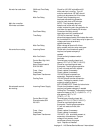
then the problem is usually with thetemperature
control board.
Temperature Control If 120 VAC is present on the
Valve temperature control board at load
terminal to neutral, check for voltageat Tempera
ture Control valve. If voltage is present, listen for
valve to open and close. Also check for
opens or shorts in the coil.
Replace if required.
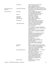
Intermittent heating Thermal Overload Of Both the main fan motor and the
Main Fan and Burner burner blower motor are equipped
Blower Motors with internal thermal protection and
will cease to operate if overheatingoccurs. As the
motors overheat and then cool, this will cause the
unitsto cycle on and off intermittently.
This may be caused by improper ventilation or
preventativemaintenance. Also, most of the
problems listed under “Oven Will Not
Heat” can cause intermittent failure.
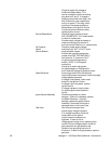
Conveyor will not run 3 Amp Fuse Check and replace if defective.
Fuseholder Check and replace if defective.
Fan Switch Check for continuity between switch
terminals.
S/N 2011821 & Above Conveyor Switch Check for continuity between switch
Refer to Page 45 terminals.
Speed Adjustment This is a 0 to 5 K ohm, 10 turn
Potentiometer. WITH POWER OFF: Remove the red, black
and white pot. leads from the motor control
board at terminalsP1, P2 and P3. With a
digital multimeter, check the ohm reading
across the red lead to the black lead. This
reading shouldbe 5 K ohms ± 5% as the pot is
rotated from low to high.Place the meter leads on
the redlead and on the white lead.Rotating the
pot. slowly, from low to high, the meter reading
should show an even transition from 0 to
5 K ohms ± 5%. There should be
no dead or open spots through out
the 10 turns of the pot.
Check all three leads to ground.
There should be no continuity to
ground. If any of the above checks
fail, replace the pot.
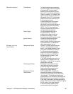
DC Motor Control Board Check for 120 VAC input to the
control board at terminals L1 and
L2. If not present, check the
conveyor switch and wiring back to the
3 amp fuse and then back to the power
source if necessary. If 120 VAC is
present at L1 and L2, check the VDC
output at terminals A+ and A-. If a
DC voltage is not present, check the
4 amp and the 1 amp fuses on the
Impinger II - 1100 Series Service Manual - International30


