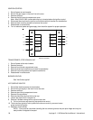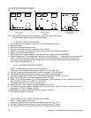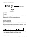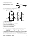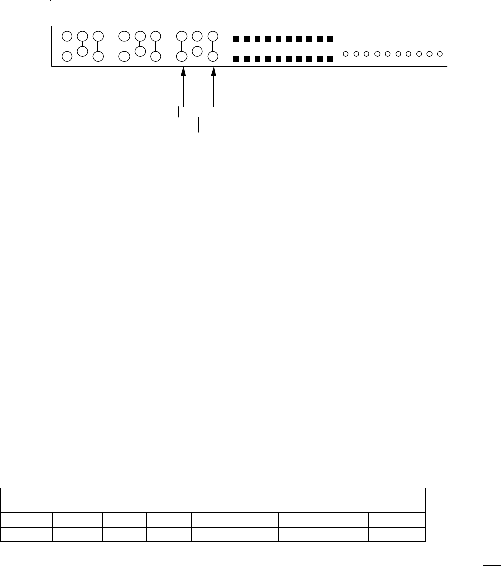
FOR DISPLAYS WITH THERMISTOR PROBE ONLY
test leads here
reading should be 26 ± .5 ohms if not, adjust.
pot. range 0-34 ohms
BOTTOM OF TIME TEMP DISPLAY
TIME CALIBRATION
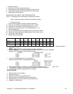
1. Be sure dip switch settings are proper.
2. Turn power on.
3. Turn conveyor on.
4. Place an object on the conveyor belt and time with a stopwatch, the elapsed time for the object to travel through
the oven (leading edge in to leading edge out).
5. Push in and hold the set button. (Discontinued on newer models)
6. Adjust time pot. (rear of display) so display agrees with your stop watch time.
7. Seal pot. with Glyptol or nail polish.
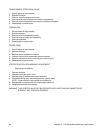
THERMISTOR PROBE REPLACEMENT
1. Shut off power at the main breaker.
2. Remove conveyor and fingers from oven.
3. Remove control compartment covers.
4. Disconnect the 2 yellow thermistor leads from terminals 9 and 10 on the rear of the time/temp. display.
5. Remove the sensing bulb of the thermistor probe from its wire form holder located at right inside rear of the
oven.
6. Install in reverse order.
NOTE: Be sure that the spring holder is holding the sensor bulb firmly. If the sensor is not held firmly,
compress the wire form slightly to increase pressure.
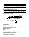
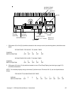
To test the thermistor probe, refer to the following chart and instructions:
OVEN TEMPERATURE
300°F 325°F 350°F 400°F 425°F 450°F 500°F 550°F
OHMS
182 138 102 62 48 38 24 16
1. Place test pyrometer thermocouple and preheat oven as specified under temperature calibration on Page D15.
2.
Disconnect the thermistor probe from terminals 9 and 10 and measure the resistance across the 2 yellow leads.
3. Refer to the above chart to determine if probe is producing the proper resistance.
EXAMPLE: The probe resistance at 500°F(260°C) should be 24 ohms.
SWITCH, DISPLAY, SET
1 Shut off power at main breaker.
Impinger II - 1100 Series Service Manual - International
62


