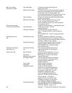
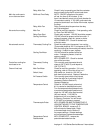
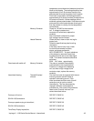
Relay, Main Fan Check if relay is operating and that the contacts r
emain closed during the 20 minute cool down.
Main fan continues to 20 Minute Time Delay NOTE: ON/OFF operation of fan switch
to run after cool down will set the timer to 20 minutes. If the
timer is accidentally reset, turn off main breaker for
15 seconds to cancel. If 120 VAC continues to be
present at terminals 2 and 3 after 20 minutes, replace
the timer.
Relay, Main Fan Relay Contacts should open when the relay
coil is de-energized.
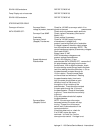
No control box cooling Main Fan Check for main fan operation. If not operating, refer
to “Oven Fan Will Not Run”.
Relay,Oven Start Check relay contacts. 120 VAC should be present.
Cooling Fan Motor 120 VAC should be present at the fan motor. If
voltage is present, check for opens or shorts.
WITH POWER OFF: Check for locked rotor
of the fan motor.
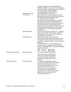
No automatic control Thermostat, Cooling Fan Check the cooling fan thermostat. box cooling
(Thermostat closes at 120°F and opens at 100°F.)
With the cooling fan thermostat pre-heated, check for
continuity. If switch is open, replace.
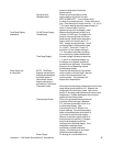
Cooling Fan Motor 120 VAC should be present at the fan
motor. If voltage is present, check for
opens or shorts.
WITH POWER OFF: Check for locked
rotor of the fan motor.
Control box cooling fan Thermostat, Cooling This normally open thermostat should
continues to run Fan close at 120°F (48.9°C) and reopen at
100°F (37.8°C).
Oven will not heat Main Fan Motor Check for main fan operation. If it is not
operating, refer to “Oven fan will not run”.
Switch, Heat With switch on, check for 120 VAC on
both terminals to neutral. Replace if defective.
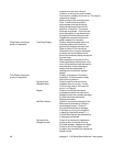
Air Pressure Switch This normally open switch should close
when the main fan is activated. Adjust if
necessary (Refer to Section D).
Replace if defective.
Temperature Control Check for 120 VAC supply at terminal
#11 to neutral on temperature control.
Turn the temperature adjustment knob
to maximum temperature position and
check for 120 VAC at the load terminal
(#9) and neutral. If 120 VAC is
present and unit is not heating, refer
to “Mercury Contactor” for next check.
If 120 VAC is not present, proceed.
Thermocouple Probe WITH POWER ON AND THERMOCOUPLE
LEADS ATTACHED TO THE TEMPERATURE
CONTROL BOARD: measure D. C.
millivolt output of these leads. Refer
to thermocouple chart in Section D
for proper readings. If these readings
are not achieved, replace thermocouple.
Temperature Control WITH POWER OFF: remove the
Potentiometer potentiometer leads from the
Impinger II - 1100 Series Service Manual - International42


