


1. Adjust the “MAX” pot. so the voltmeter indicates 15.8 to 15.9 VDC.
2. Turn the speed control pot. to its minimum speed setting.
3. Adjust the “MIN” pot. so the volt meter indicates 0.7 to 0.9 VDC.
4. Reset the speed control pot. to its maximum speed setting and check if voltage is still at 15.8 to 15.9 VDC.
Readjust if necessary.
5. Reset the speed control pot. to its minimum speed setting and check if voltage is still at 0.7 to 0.9 VDC. Read-
just if necessary.
6. If readjustment of either the “MAX” or “MIN” pot. was necessary, the opposite must always be checked until
both “MIN” and “MAX” are in proper adjustment.
7. Measure the speed of the conveyor and adjust the time/temp. display if necessary.
8. Seal pots with Glyptol or nail polish.
NOTE: Occasionally a new board (Style 2 and 3 only) is so far out of adjustment that you will be unable to
adjust to the correct voltage. To correct, turn both the “MAX” and MIN” pots 10 turns in either direction and then
5 turns in opposite direction. This will center the pots and allow them to be calibrated. If after this procedure,
the board will not adjust, it is probably defective.
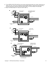
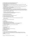
REVERSAL OF CONVEYOR BELT - D.C. Motor
All ovens leaving our plant are wired to operate conveyors from left to right. To
reverse conveyor direction, use the following procedure.
1. Turn off power and remove conveyor.
2. Remove front control compartment cover.
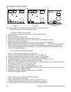
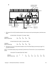
3. Refer to control board drawing to identify terminal connections.
4. Reverse wires fastened to terminals A+ and A-.
5. Reverse wires fastened to terminals T1 and T2.
Both set of leads must be reversed or oven will run at maximum speed with no speed
adjustment possible.
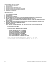
POTENTIOMETER, CONVEYOR SPEED CONTROL
1. Turn off power.
2. Remove conveyor.
3. Remove front control compartment cover.
4. Remove adjustment knob. Two allen set screws.
5. Remove exterior friction shaft retainer from pot shaft. Turn counter-clockwise to loosen.
6. Remove pot shaft from hole and disconnect leads from motor control board.
7. Assemble in reverse order.
8. If a new pot. is installed, the motor control board must be calibrated.
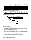
MINI BREAKER 0.2 AMP
1. Shut off power at main breaker.
2. Remove conveyor.
3. Remove control box covers.
4. Remove knurled mounting ring and disconnect wiring.
5. Reassemble in reverse order.
6. Push button to set.
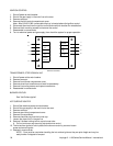
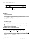
BEARING, CONVEYOR
1. Remove conveyor from oven and place on a flat work surface.
2. Remove connecting links from conveyor belting. See Installation and Operating Instructions manual.,
3. Move drive shaft or idle shaft toward end of conveyor, and shaft with bearings will now slip out of holding
bracket.
Replace bearing and reassemble.
Impinger II - 1100 Series Service Manual - International 59