© 2007 by Stephen Beck V1.0 Page 12 of 19 Use at your Own Risk
3. This is where you’ll need to get help from a friend if you don’t know how to solder. Read this description
fully before starting.
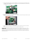
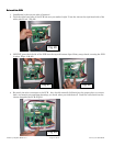
4. Using your soldering iron, and de-soldering bulb for suction, one cap at a time, melt each connection, squeeze
the bulb, and place it right on the molten solder and quickly un-squeeze the bulb while keeping it in place.
This acts like a mini vacuum cleaner and removes the solder from the connection. You may have to do this a
couple times to get as much solder off as possible. If the bulb gets clogged poke it clear with a toothpick or
small nail. Don’t keep the soldering iron on too long as it may damage the PCB.
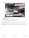
5. With most of the solder removed, re-heat the 2 connections until the solder melts and then gently rock the
cap back and forth from the other side pulling the cap out. You may have to heat one connection at a time
and pull the cap up on that side. You may also need a helper to hold the PCB and pull on the cap for you.
Be careful not to burn your friend (perhaps they should be wearing heavy work gloves just in case..). I don’t
have a picture of this since it required all my hands and fingers to get it off, leaving none for the camera.
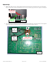
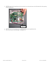
6. With the cap removed, if there is an open hole, great. If there is still solder in the hole, find a toothpick, re-
heat the hole till the solder melts, then gently stick the wooden toothpick through the hole, remove the
soldering iron and let it cool. Once the solder hardens, remove the toothpick. Remember that just because
the solder is hard does not make if safe to touch – it’s still quite hot. Blowing on it speeds the cooling
process..
7. You should be left with 4 holes in the PCB and 2 caps apart from the PCB.
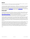
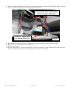
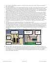
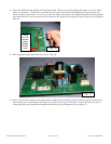
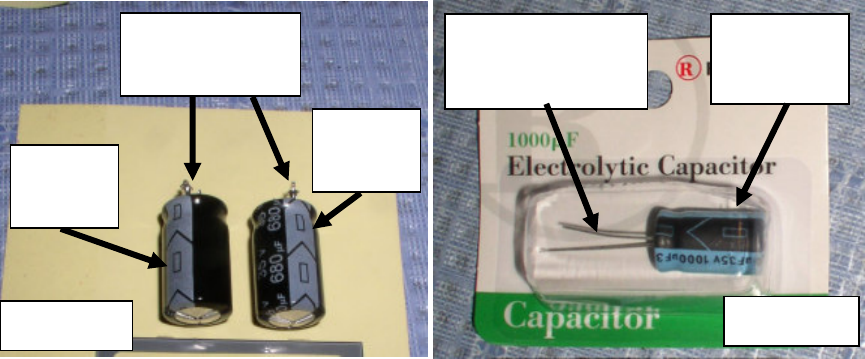
8. Electrolytic caps have a “plus” (+) and a minus (-) just like your car. And just like your car, if you hook them
up backwards, dire things happen. So look at the caps you took out, and are about to put in. You’ll see a
“minus sign” or dash on one side. The wire coming out next to the minus side is the negative. The opposite
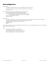
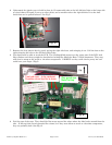
is the positive. (Fig 14) One of the new RS caps is on the right. (Fig 15) Same type of marking, slightly
different color combinations. See the arrow in the marking pointing to the bottom of the cap and the actual
wire lead.
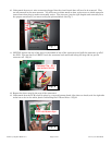
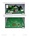
9. With the “minus” lead of the caps towards the center of the board, push the wire leads thru the holes and
seat the cap flat on the PCB. You can bend the wire leads out 45
o
to hold the caps in place for when you turn
the PCB upside down. Note that it does not matter which cap goes into either set of holes, only that the
positive leads go into the holes towards the edge of the board, and the negative leads go into the holes
towards the middle of the board.
Fig. 14
© 2007 Stephen Beck
Negative (-)
terminals
Minus
signs
Minus
signs
Minus
sign
Negative (-)
terminal
© 2007 Stephen Beck
Fig. 15