


100
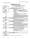
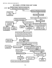
P. Burner and Gas Train Troubleshooting
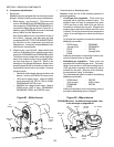
1. Burner Blower Motor
If there is 110V (or 208/240V, as appropriate) to the
motor terminals, it should be running. If the motor is
not running, replace it.
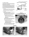
2. Burner Blower Motor Centrifugal Switch (or air pressure
safety switch)
If the burner blower motor is running at top speed, and
you cannot measure 24V across the supply terminals
of the ignition module, the centrifugal switch is not clos-
ing properly and is either loose or defective.
For 120V burner blower motors with an internal cen-
trifugal switch, tighten the switch. If this fails to correct
the problem, replace the motor.
For 208/240V burner blower motors with a separate air
pressure safety switch, refer to Air Pressure Safety
Switch on Page 82 to troubleshoot the switch.
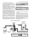
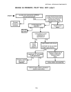
3. Relay
Connect a voltmeter across the supply terminals on
the relay. The reading should be 24V. If you do not get
a 24V reading, the transformer should be replaced.
lf 24V is present at the relay, and if after 15 to 45 sec-
onds you do not get 110V (or 208/240V, as appropri-
ate) on terminal 3 of the relay, replace the relay.
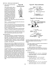
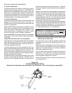
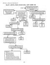
4. Main Gas Valve and Ignition Module
If 24V can be measured across the ignition module
supply terminals, there should also be 24V between
terminals PV and MV/PV on the gas control module.
If you have a 24V reading, the pilot valve should be
open and the spark should be on to ignite the pilot gas.
When the pilot gas has ignited, the main burner should
ignite. If not, check MV terminal to ground and see if
24V is present. If no voltage is present, replace the
ignition module.
It is possible to have a pilot on, but have the spark
continue to try to light the pilot. If this continues for
more than 30 seconds, then it should be assumed that
the flame sensor is not working properly. This can be
easily checked. Refer to Control Module Flame Sensor
Test on the next page.
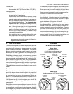
A reading of 2.0 mA or greater should be obtained. If a
poor reading is obtained, the pilot flame and sensor are
probably not making good contact. This will keep the
main valve from opening. Refer to the section on flame
rectification. If the microamp reading is good and 24V
cannot be obtained at terminal MV then the ignition
module should be replaced.
SECTION 3 - SERVICING COMPONENTS
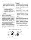
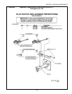
O. Gas Conversion Kits
Ovens can be converted from natural gas to propane opera-
tion, or from propane to natural gas operation, by the instal-
lation of the appropriate Gas Conversion Kit. Refer to Part
Number Reference - Gas Orifices and Gas Conversion Kits
on Page 91 for a listing of kit part numbers.
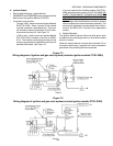
Converting the oven to operate on a different gas type gen-
erally requires:
Replacement of the regulator spring on the combina-
tion gas control valve. The spring is located under-
neath the pressure regulator screw. Note that on
PS360EWB and PS360WB70 ovens equipped with the
Midco burner, replacement of the regulator spring is
not necessary.
Replacement of the main orifice, pilot orifice, and by-
pass orifice.Note that ovens equipped with the modu-
lating gas system do not use a bypass orifice.
Adjustment of the main and pilot gas pressures.
Documenting the gas conversion using the labels and
tags supplied in the kit.
Instructions for the gas conversion kits are provided in the
Appendices section.