


65
10
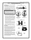
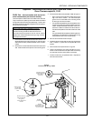
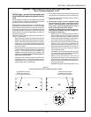
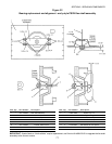
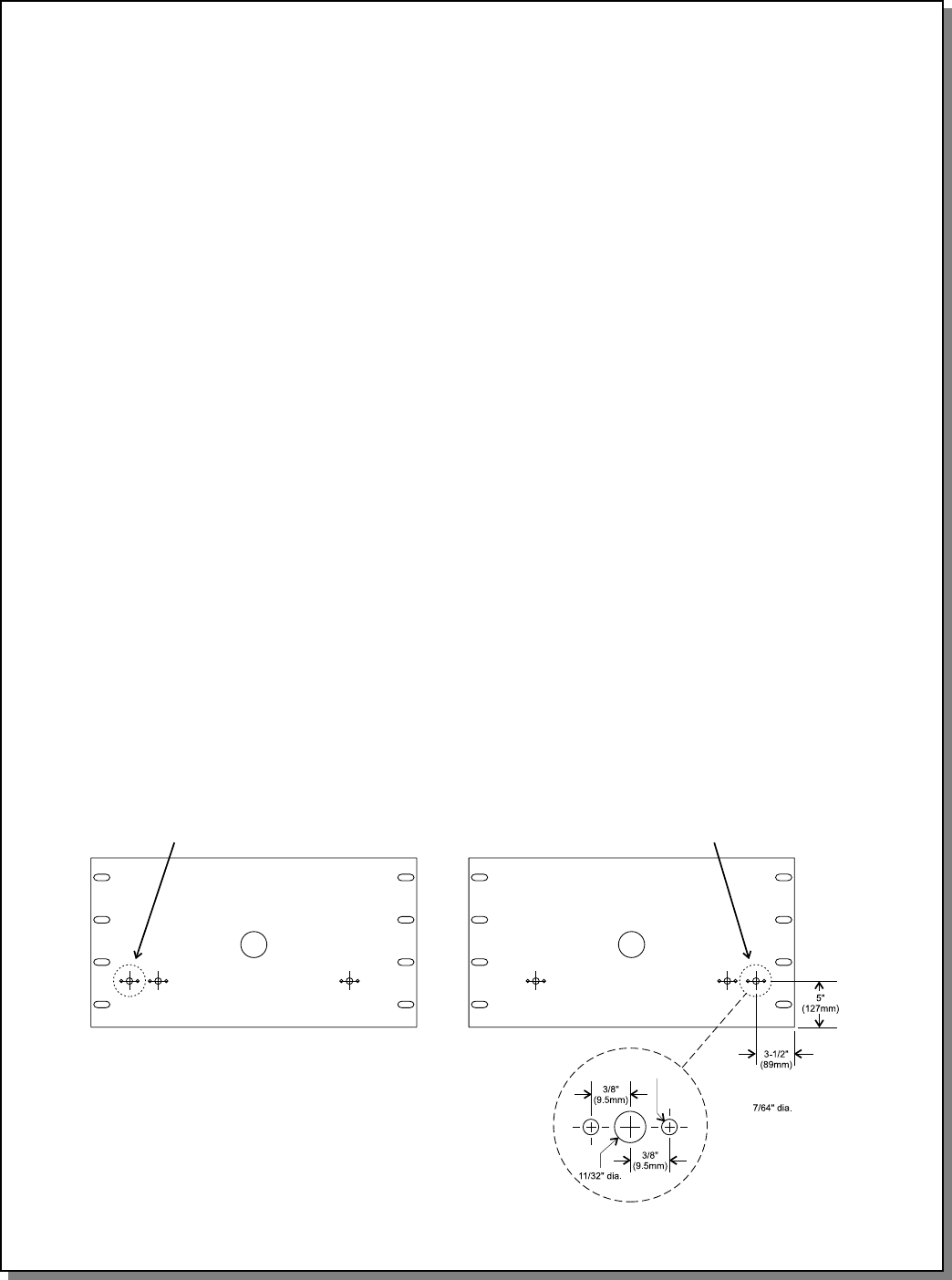
Figure 13
Location of High Limit Thermocouple Mounting Hole - PS570S
High limit thermocouple
position for ovens with
LEFT-TO-RIGHT conveyors
High limit thermocouple
position for ovens with
RIGHT-TO-LEFT conveyors
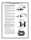
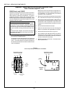
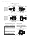
PS570S (late) - rear wall thermocouples with
left-side AND right-side terminal block connec-
tions
Thermocouples on these ovens are located on the rear wall
and are secured in place by two screws that are inserted
through the holes in the thermocouple flange.
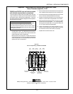
Most of these ovens have either three or four thermocouples,
all installed in the back wall of the oven. The thermocouple
at the extreme exit end of the oven is the high limit thermo-
couple, while all other thermocouples send their signals to
the digital temperature controller. The thermocouple sup-
plied in this Kit can be used to replace ANY of the thermo-
couples on these ovens.
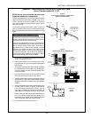
Some PS570S ovens are equipped with only two thermo-
couples. In these ovens:
The thermocouple on the right side of the oven has two
leads and sends its signal to the temperature controller.
The thermocouple on the left side of the oven is a dual-
function unit. It has FOUR LEADS and sends indi-
vidual signals to the temperature controller and the high
limit control module.
Installing this Kit will replace BOTH thermocouples with
current three-lead versions located on the back wall of
the oven. The Kit also requires the installation of a
THIRD thermocouple to act as a high limit sensor. Be-
cause of this, you will need three separate thermo-
couple kits for these ovens.
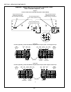
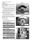
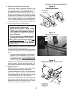
1. Remove the rear shrouds and open the blower motor
compartment doors. This allows access to the ther-
mocouples (on the rear wall) and terminal blocks (in-
side the blower motor compartments).
2. Remove the screws that hold the thermocouple to the
wall. Slide the thermocouple out of its mounting hole.
3. Disconnect the thermocouple leads. Remove and dis-
card the thermocouple.
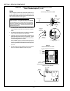
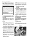
4. Perform Step 4 ONLY if you are installing a high
limit thermocouple and no mounting hole is
present. This would be the case if the oven for-
merly used a four-lead thermocouple to send a
signal to the high limit control module.
Temperature-sensing thermocouples for these ov-
ens should be installed in the two existing ther-
mocouple mounting holes.
Refer to Figure 13. Measure and scribe marks in
the rear wall of the oven for drilling the high limit
thermocouple mounting hole. Make sure that your
measurements begin at the edges of the rear pan-
els, and NOT and the outer edges of the oven!
Drill the new high limit thermocouple mounting hole
using an 11/32 (8.73mm) D x 8 (203mm) L bit.
Be sure to drill through all three walls of the oven.
Drill the two screw mounting holes for the high limit
thermocouple using a 7/64 (2.78mm) bit. Tap the
holes using a #6-32 tap.
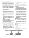
If necessary, remove the end plugs and air fingers
from the oven to access the areas around the new
high limit thermocouple mounting hole.
Vacuum out ALL drill shavings. If the oven is
equipped with a screen over the openings for the
lower air fingers, use a flexible hose extension on
the vacuum to reach the shavings through the up-
per air finger openings.
Reinstall the air fingers and end plugs onto the oven.
Appendix - Instructions for Service Kits 33984 and 33985 -
Oven Thermocouple Kit, 11/01
SECTION 3 - SERVICING COMPONENTS