


66
11
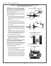
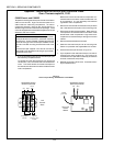
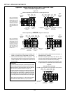
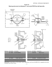
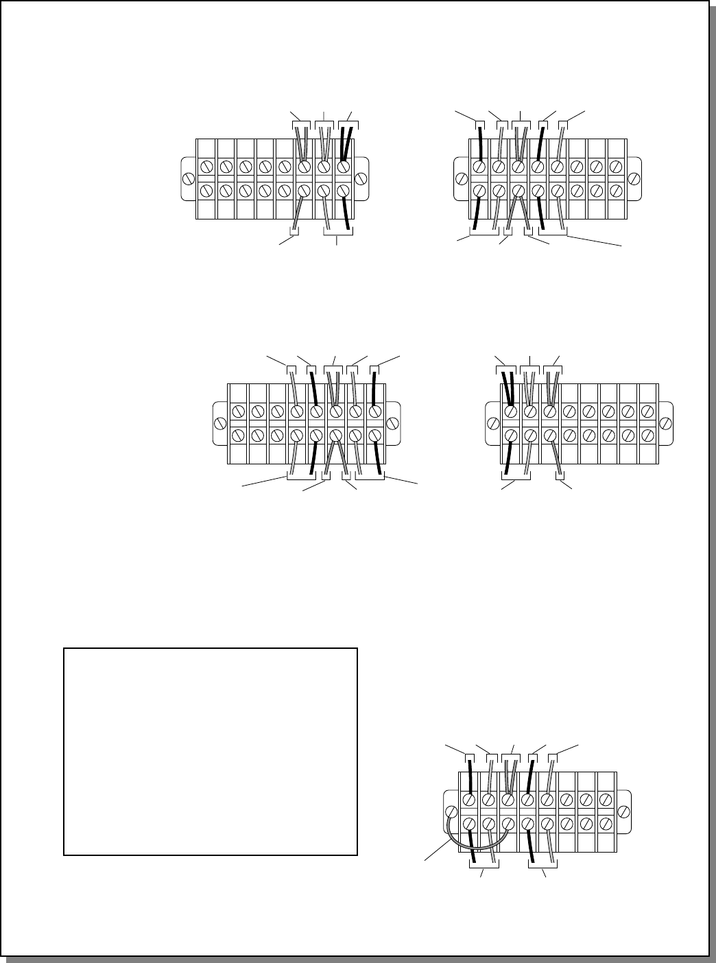
Figure 14a
Thermocouple Wiring - PS570S (Late) - Left to Right Conveyor
Red
(temp)
White
(temp)
Ground
leads
To temperature
controller
To high limit
control module
White
(hi lim)
Red
(hi lim)
Ground
leads (all)
White
(temp)
Red
(temp)
To mounting screw
for high limit
control module
To ground
terminal on temp
controller
To temperature
controller
To ground
terminal on temp
controller
Red
(temp)
White
(temp)
Ground
leads (all)
To temperature
controller
To high limit
control module
White
(hi lim)
Red
(hi lim)
Ground
leads
White
(temp)
Red
(temp)
To mounting screw
for high limit
control module
To ground
terminal on temp
controller
To temperature
controller
To ground
terminal on temp
controller
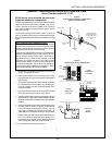
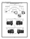
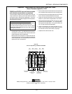
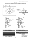
Figure 14b
Thermocouple Wiring - PS570S (Late) - Right to Left Conveyor
NOTE: This configuration
shows leads for three
temperature-sensing
thermocouples - two on the
left side, and one on the
right. Ovens with only two
temperature-sensing
thermocouples will have a
single set of leads on the
left terminal block, instead
of the two sets that are
shown.
NOTE: This configuration
shows leads for three
temperature-sensing
thermocouples - two on the
right side, and one on the
left. Ovens with only two
temperature-sensing
thermocouples will have a
single set of leads on the
right terminal block,
instead of the two sets
that are shown.
Left
Terminal
Block
Right
Terminal
Block
Left
Terminal
Block
Right
Terminal
Block
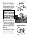
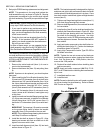
5. Install the new thermocouple into its mounting hole.
Fasten it in place with the supplied #6 x 3/8 screws.
6. Wire the thermocouple as shown in Figure 14. The
thermocouples should be wired to the terminal block
inside the blower motor compartment closest to the
thermocouple.
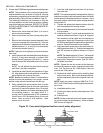
IMPORTANT
As you wire the thermocouples, check that ground leads
run from the terminal blocks inside the blower motor com-
partments to BOTH the temperature controller AND the
high limit control module, as shown in Figure 14.
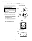
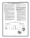
If the ground leads to the front compartment of the oven
are NOT present - for example, on an oven that previ-
ously used the older-style 2-lead or 4-lead thermocouples
- it is acceptable to use a single chassis ground wire to
the mounting screw for the terminal block. See Figure
15.
A good ground connection for the thermocouples
uninsulated lead is REQUIRED for proper operation!
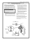
7. If you will be replacing additional thermocouples, re-
peat Steps 2-6 as necessary.
8. Use the kit-supplied nylon clamp and #10-16 x 3/4
screw to secure the thermocouple leads so that they
will clear the shrouds, blower belts, and pulleys.
9. Close the machinery compartment and blower motor
compartment doors. Replace all shrouds onto the oven.
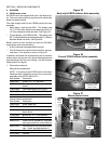
Figure 15
Alternate ground lead wiring
Use ONLY if ground leads to front compartment are not present.
To temperature
controller
To high limit
control module
White
(hi lim)
Red
(hi lim)
Ground
leads (all)
White
(temp)
Red
(temp)
New chassis
ground wire
Appendix - Instructions for Service Kits 33984 and 33985 -
Oven Thermocouple Kit, 11/01
SECTION 3 - SERVICING COMPONENTS